


28 RT-PRC031-EN
This section outlines a step-by-step
procedure that may be used to select
a Trane air handler. The sample
selection is based on the following
conditions:
Summer Design:
• Summer outdoor design
conditions - 95 DB/76 WB
ambient temperature
• Summer room design
conditions -78 DB/65 WB
• Total cooling load - 980 MBH
(81.6 tons)
• Sensible cooling load - 735 MBH
(61.25 tons)
• Outdoor air ventilation load -
154.0 MBH (12.8 tons)
• Return air temperature -
78 DB/65 WB
Winter Design:
• Winter outdoor design condition
is 0°F.
• Total return air temperature is
70°F.
• Total heating load - 720 MBH
• Winter outdoor air ventilation
load - 288.6 MBH
• Total winter heating load -
1008.6 MBH
Air Delivery Data:
• Supply fan CFM - 36000 CFM
• Supply duct static pressure - 1.86
2.2 in wg
• Minimum outdoor air ventilation
- 3600 CFM
• Exhaust fan CFM - 36000 CFM
• Return air duct negative static
pressure - 0.3 in wg
Electrical Characteristics:
• Voltage/cycle/phase - 460/60/3
Unit Accessories:
• Gas fired heat exchanger - High
Heat
• Downflow supply and upflow
return
• High Efficiency Throwaway
filters
• Economizer
• Modulating 100 percent exhaust
Cooling Capacity Selection:
Step 1 - Coil and Fan
Selection
A summation of the peak cooling
load and the outside air ventilation
load shows: 980 MBH + 154.0 MBH =
1134.0 MBH required unit capacity.
The supply fan air flow requirement
is 36,000 cfm.
From Table 10, p. 39, a 4 row W coil
with 144 fpf (fins per foot) and no
turbulators at 80 DB/67 WB and
36000 supply air cfm has a total
cooling capacity of 1336 MBH and
sensible cooling capacity of 969
MBH. With chilled water coil capacity
data at 80 DB/67 WB only, TOPSS is
required for an accurate selection at
other conditions. TOPSS is also
required to select the correct water
control valve for proper flow control,
in this case a 2 ½ "or 3" valve.
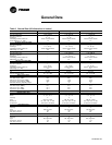
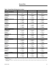
Table 3, p. 34 - General Data shows
that air handler "C" can provide
36000 total supply CFM.
Thus air handler "C" with a 4 row 144
fpf W coil having no turbulators at
45°F entering water and a 10°F rise
with a 2 ½" valve is selected. The coil
water flow rate is 266 GPM and
water side pressure drop is 13.7 ft of
water.
Step 2 - Cooling Coil Entering
Conditions
Mixed air dry bulb temperature
determination:
Using the minimum percent of OA
(3600 CFM ÷ 36000 CFM = 10
percent), determine the mixture dry
bulb to the cooling coil.
RADB + % OA (OADB - RADB) = 78 +
(0.10) (95 - 78) = 78 + 1.5 = 79.5°F
Approximate wet bulb mixture
temperature:
RAWB + % OA (OAWB - RAWB) = 65
+ (0.10) (76 - 65) = 65 + 1.1 = 66.1°F
Step 3 - Determine Supply
Fan Motor Heat Gain
Having selected air handler casing
"C" with a 4 row 144 fpf W coil and
no turbulators, the supply fan BHP
can be calculated.
The supply fan motor heat gain must
be considered in final determination
of unit capacity.
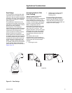
Supply Air Fan
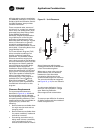
Determine unit total static pressure
at design supply CFM:
Using total of 36000 CFM and total
static pressure of 4.0 inches, enter
Table 17, p. 48. The table shows 40.4
BHP with 1097 rpm required for the
36" supply fan.
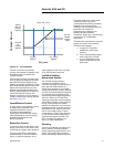
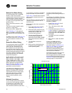
From Figure 17, p. 30 supply fan
motor heat gain = 109.0 MBH, or
109.0 MBH x 1000 ÷ ( 36000 CFM x
1.085 ) = 2.8°F supply fan motor heat
Step 4 - Determine Total
Required Cooling Capacity
Required capacity = Total peak load +
OA load + supply air fan motor heat
Required capacity = 980.0 + 154.0 +
109.0 = 1243.0 MBH
Step 5 - Determine Unit
Capacity
The coil entering air conditions of
79.5 DB/66.1 WB are close to the
capacity data table at 80 DB/67 WB
used for the original selection. The
unit capacity with the 4 row 144 fpf
W coil with no turbulators at 45°F
entering water a 10°F rise, 36000 cfm
supply air flow and 10% outside air
Supply Duct Static Pressure 2.2"
Chilled Water Coil Table 33, p. 72 0.64"
Return Duct Negative Static
Pressure
0.30"
Heat Exchanger Table 34, p. 72 0.03"
Throwaway Filter Table 35, p. 73 0.26"
Return Damper Table 34, p. 72 0.34"
Economizer Damper
(i)
Table 34,
p. 72
(i)
Add either the economizer damper value or
return damper value, depending on which
static pressure is greater. (Do not use both.)
0.57"
Unit Total Static Pressure 4.0"
Selection Procedure