72 RT-PRC031-EN
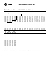
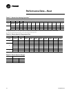
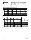
Table 33 Chilled Water Coil Airside Pressure Drop (in H
2
0)
Chilled Water Coil
Airside Pressure Drop (in H
2
O)
2 row 4 row 6 row 8 row
Casing CFM 80 fpf
108
fpf
144
fpf
168
fpf
80 fpf
108
fpf
144
fpf
168
fpf
80 fpf
108
fpf
144
fpf
168
fpf
80 fpf
108
fpf
144
fpf
168
fpf
A, B, C
16000 0.03 0.06 0.09 0.12 0.09 0.13 0.19 0.25 0.13 0.19 0.29 0.36 0.18 0.27 0.39 0.49
20000 0.06 0.09 0.13 0.16 0.13 0.19 0.27 0.34 0.20 0.28 0.40 0.50 0.27 0.38 0.54 0.68
23000 0.07 0.11 0.16 0.19 0.17 0.24 0.33 0.41 0.25 0.35 0.49 0.61 0.34 0.48 0.67 0.83
28000 0.10 0.15 0.21 0.26 0.24 0.33 0.44 0.54 0.35 0.49 0.66 0.81 0.48 0.67 0.89 1.10
33000 0.14 0.19 0.26 0.32 0.31 0.43 0.57 0.69 0.46 0.64 0.85 1.03 0.63 0.87 1.14 1.39
38000 0.18 0.24 0.33 - 0.40 0.54 0.70 - 0.59 0.80 1.04 - 0.81 1.09 1.41 -
43000 0.22 0.29 - - 0.49 0.65 - - 0.73 0.98 - - 0.99 1.34 - -
45000 0.23 0.31 - - 0.53 0.70 - - 0.78 1.05 - - 1.07 1.44 - -
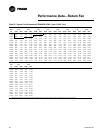
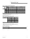
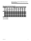
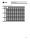
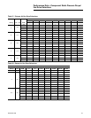
Table 34 Component Static Pressure Drops (in. H
2
O)
Gas Heating
Hydronic Heating Coil
Data
Electric
Heating
(Horiz.) Low Heat
Medium
Heat High Heat
Hot Water
Coil Steam Coil
Casing
CFM
All kw's
(i)
(i)
There is no pressure drop with Electric Heat DF configuration
DF Hz DF Hz DF Hz High Low High Low
Return
Damper
Econo
Damper
(wide
open in
H
2
0)
Traq
Damper
(wide
open in
H
2
0)
A, B, C
16000 0.01 0.01 0.10 0.01 0.12 0.01 0.14 0.13 0.08 0.12 0.08 0.06 0.11 0.19
20000 0.02 0.01 0.16 0.01 0.19 0.01 0.22 0.17 0.11 0.16 0.11 0.09 0.15 0.26
23000 0.03 0.01 0.21 0.01 0.26 0.01 0.30 0.23 0.15 0.22 0.16 0.13 0.23 0.38
28000 0.04 0.02 0.31 0.02 0.38 0.02 0.44 0.32 0.21 0.31 0.22 0.20 0.34 0.57
33000 0.06 0.02 0.42 0.02 0.53 0.02 0.61 0.42 0.28 0.41 0.30 0.28 0.47 0.79
38000 0.07 0.03 0.56 0.03 0.70 0.03 0.81 0.53 0.36 0.52 0.39 0.38 0.63 1.05
43000 0.10 0.04 0.72 0.04 0.89 0.04 1.03 0.65 0.45 0.65 0.49 0.49 0.81 1.34
45000 0.10 0.04 0.79 0.04 0.98 0.04 1.13 0.71 0.49 0.70 0.53 0.53 0.89 1.47
Performance Data—Component
Static Pressure Drops/Fan Drive
Selections


