


RT-PRC031-EN 27
Applications Considerations
Duct Design
It is important to note that the rated
capacities of the air handler can be
met only if the air handler is properly
installed in the field. A well-designed
duct system is essential in meeting
these capacities.
The satisfactory distribution of air
throughout the system requires that
there be an unrestricted and uniform
airflow from the air handler
discharge duct. This discharge
section should be straight for at least
several duct diameters to allow the
conversion of fan energy from
velocity pressure to static pressure.
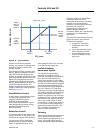
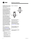
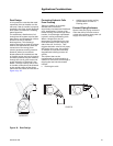
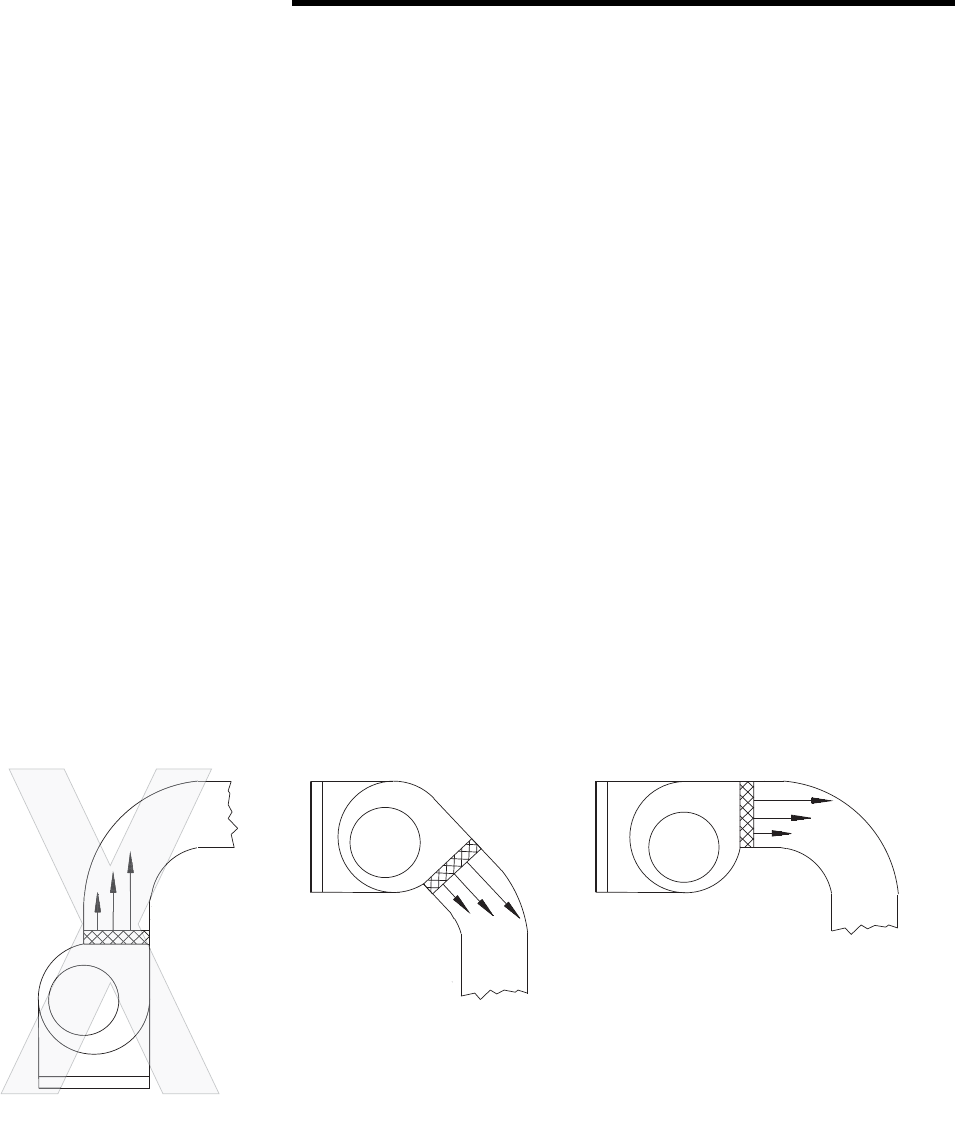
However, when job conditions
dictate elbows be installed near the
air handler outlet, the loss of capacity
and static pressure may be reduced
through the use of guide vanes and
proper direction of the bend in the
elbow. The high velocity side of the
air handler outlet should be directed
at the outside radius of the elbow
rather than the inside as illustrated in
Figure 16, p. 27.
Figure 16. Duct Design
IMPROPER
PROPER
Protecting Hydronic Coils
From Freezing
Taking in outdoor air to satisfy
Standard 62’s ventilation
requirement increases the likelihood
of air stratification. If a layer of air
below freezing moves through the air
handler, it can damage unprotected
hydronic cooling and heating coils.
When a dangerously low air
temperature is detected by the low-
limit thermostat on the entering-air
side of the coil, it will trip. That
triggers the water valve to fully open,
the supply fan to stop, the outdoor
air damper to close and ultimately
degrades the building’s indoor air
quality.
Two options that can be
implemented to continue taking in
outdoor air and avoid coil damage or
tripping the low-limit thermostat
include:
• Draining the coils
• Adding glycol to the cooling
system water to lower its
freezing point
External Piping Enclosure
Space inside the piping enclosure
limits the ability to house control
valves and actuators along with coil
supply and return piping.