


18 RT-PRC031-EN
Controls VAV and CV
– Supply Fan IGV/ Supply Fan
VFD - Max (if so equipped)
– Exhaust Fan - On; Exhaust
Dampers Open (if so
equipped)
– OA Dampers - Open; Return
Damper - Closed
– Heat - All heat stages off;
Mod Heat output at 0 vdc
– Occupied/Unoccupied/VAV
box output - Energized
– VOM Relay - Energized
– Preheat Output - Off
– Return Fan - On; Exhaust
Dampers - Open (if so
equipped)
– Return VFD - Max (if so
equipped)
– OA Bypass Dampers - Open
(if so equipped)
– Exhaust Bypass Dampers -
Open (if so equipped)
5. PURGE with duct pressure
control sequence “E”
This sequence can be used when
supply air control is required for
smoke control.
– Supply Fan - On
– Supply Fan IGV / Supply Fan
VFD - (If so equipped)
Controlled by Supply Air
Pressure Control function;
Supply Air Pressure High
Limit disabled
– Exhaust Fan - On; Exhaust
Dampers Open (if so
equipped)
– OA Dampers - Open; Return
Damper - Closed
– Heat - All heat stages off;
Mod Heat output at 0 vdc
– Occupied/Unoccupied/VAV
box output - Energized
– VOM Relay - Energized
– Preheat Output - Off
– Return Fan - On; Exhaust
Dampers - Open (if so
equipped)
– Return VFD - Max (if so
equipped)
– OA Bypass Dampers - Open
(if so equipped)
– Exhaust Bypass Dampers -
Open (if so equipped)
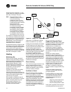
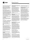
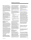
Human Interface Panel (HI)
The Human Interface (HI) Panel
provides a 2 line X 40 character clear
English liquid crystal display and a 16
button keypad for monitoring,
setting, editing and controlling. The
Human Interface Panel is mounted in
the unit's main control panel and is
accessible through an independent
door. See Figure 13, p. 18
The optional remote mount version
of the Human Interface (RHI) Panel
has all the functions of the unit
mount version except Service Mode.
To use a RHI the unit must be
equipped with an optional Inter-
Processor Communications Bridge
(IPCB) module. The RHI can be
located up to 1000 feet from the unit.
A single RHI can be used to monitor
and control up to four (4) air
handlers, each containing an IPCB.
Human Interface Panel Main
Menu
• STATUS - used to monitor all
temperatures, pressures,
humidities, setpoints, input and
output status.
• CUSTOM - allows the user to
create a custom status menu
consisting of up to four (4)
screens of the data available in
the Status menu.
• SETPOINTS - used to review and/
or modify all the factory preset
Default setpoints and setpoint
source selections.
• DIAGNOSTICS - used to review
active and historical lists of
diagnostic conditions. Over one
hundred different diagnostics
can be read at the Human
Interface Panel. The last 20
unique diagnostics can be held
in an active history buffer log.
Figure 13. Human Interface
Panel (HI)
• SETUP - Control parameters,
sensor source selections,
function enable/disable, output
definitions, and numerous other
points can be edited in this
menu. All points have factory
preset values so unnecessary
editing is kept to a minimum.
• CONFIGURATION - Preset with
the proper configuration for the
unit as it ships from the factory,
this information would be edited
only if certain features were
physically added or deleted from
the unit. For example, if a field
supplied Ventilation Override
Module was added to the unit in
the field, the unit configuration
would need to be edited to
reflect that feature.
• SERVICE - used to selectively
control outputs (for fans, damper
position, etc.) for servicing or
troubleshooting the unit. This
menu is accessible only at the
unit mounted Human Interface
Panel.
Generic Building Automation
System Module (GBAS 0-5
vdc)
The Generic Building Automation
System Module (GBAS 0-5vdc) is
used to provide broad control
capabilities for building automation
systems other than Trane's Tracer™
system. The following inputs and
outputs are provided:
Analog Inputs - Four analog inputs,
controlled via a field provided
potentiometer or a 0-5 vdc signal,
that can be configured to be any of
the following:
1. Occupied Zone Cooling Setpoint
(CV only)
2. Unoccupied Zone Cooling
Setpoint (CV only)
3. Occupied Zone Heating Setpoint
(CV only)
4. Unoccupied Zone Heating
Setpoint (CV only)
5. Supply Air Cooling Setpoint (VAV
only)
6. Supply Air Heating Setpoint (VAV
only)
7. Space Static Pressure Setpoint