


RT-PRC031-EN 85
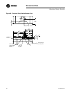
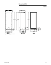
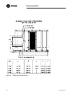
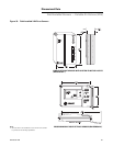
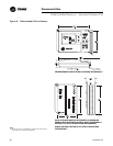
Dimensional Data
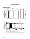
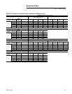
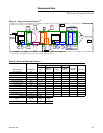
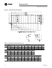
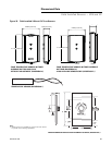
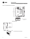
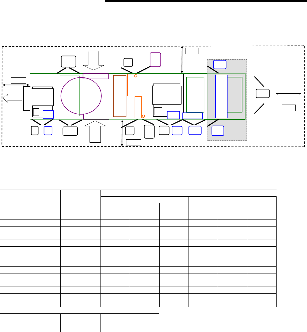
Minimum Clearance Details
Figure 31. Minimum Required Clearance
(i)
(i)
Unit drawing is representative only and may not accurately depict all models.
Table 46 Minimum Required Clearance
Unit Option Selection (Door Swing Ft. and In.)
Standard VFD Heat
Door Location Availability A,B,C
Return/
Exhaust Supply
Electric/
Hot Water/
Steam
Two-side
Access Final Filter
Exhaust Motor Std 2' 2" * * * * *
Exhaust VFD As Req. * 2' 2" * * * *
Filter (Front) Std2' 8"*****
Filter (Rear) Option * * * * 2’ 2" *
Cooling Coil (Front) Std 2' 2" * * * * *
Cooling Coil (Rear) Std 2' 8" * * * * *
or Cooling Coil (Rear)Option******
Supply Motor Std2' 8"*****
Supply VFD As Req. * * 2' 2" * * *
Heat (Left & Right) As Req. * * * 2' 2" * *
Final Filter (Front) As Req. * * * * * 2' 2"
Final Filter (Rear) As Req. * * * * * 2' 2"
Control Box (L & R)Std3' 2"*****
Minimum Required Clearance (Ft.)
AH_L AH_R Exh
Control
Box
8’ 8’ 8’ 6’
Blank Section
Cool
Coil
(F)
Fltr
(F)
Sup
Mtr
Sup
VFD
Fltr
(R)
Cool
Coil
(R)
Heat
(L&R)
OptionStd
As Req. As Req.StdStd
Std
Rtn
Mtr
Rtn
VFD
As Req.
Std
ER Fltr
(L&R) (F)
Std
ER Fltr
(L&R) (R)
Std
Final
Filter
Fnl
Fltr (F)
As Req.
Fnl
Fltr (R)
As Req.
Filters
VFD
Heat
VFD
Ctrl Box
(L&R)
Std
Exhaust
Fresh
Air
Fresh
Air
Exh
AH R
AH L
C Box