


RT-PRC031-EN 11
VAV Units Only
Note: When noted in this sequence
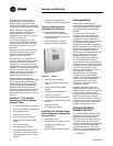
“Human Interface Panel,” the
reference is to both the unit
mounted and remote
mounted Human Interface
Panel. All setpoint
adjustments can be
accomplished at the unit or
Remote Human Interface
Panel.
Supply Air Pressure
Control
Inlet Guide Vanes Control
Inlet guide vanes are driven by a
modulating 0-10 vdc signal from the
Rooftop Module (RTM). A pressure
transducer measures duct static
pressure, and the inlet guide vanes
are modulated to maintain the
supply air static pressure within an
adjustable user-defined range.
The range is determined by the
supply air pressure setpoint and
supply air pressure deadband, which
are set through the Human Interface
Panel or BAS/Network.
Inlet guide vane assemblies installed
on the supply fan inlets regulate fan
capacity and limit horsepower at
lower system air requirements.
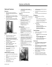
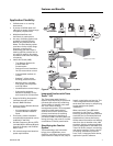
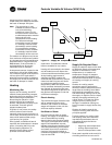
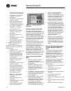
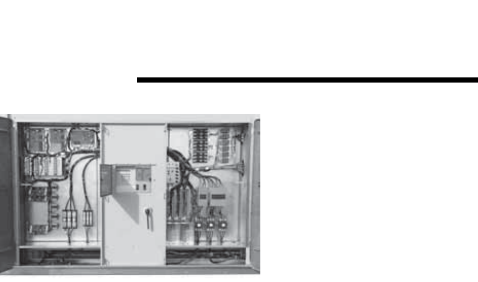
Figure 11. IntelliPak™ II Control Panel
When in any position other than full
open, the vanes pre-spin intake air in
the same direction as supply fan
rotation. As the vanes approach the
full-closed position, the amount of
“spin” induced by the vanes
increases at the same time that
intake airflow and fan horsepower
diminish. The inlet guide vanes will
close when the supply fan is shut
down, except during night setback.
Variable Frequency Drive
(VFD) Control
Variable frequency drives are driven
by a modulating 0-10 vdc signal from
the Rooftop Module (RTM). A
pressure transducer measures duct
static pressure, and the VFD is
modulated to maintain the supply air
static pressure within an adjustable
user-defined range.
The range is determined by the
supply air pressure setpoint and
supply air pressure deadband, which
are set through the Human Interface
Panel or BAS/Network.
Variable frequency drives provide
supply fan motor speed modulation.
The drive will accelerate or
decelerate as required to maintain
the supply static pressure setpoint.
When subjected to high ambient
return conditions the VFD will reduce
its output frequency to maintain
operation.
Bypass control is offered to provide
full nominal airflow in the event of
drive failure.
Supply Air Static Pressure
Limit
The opening of VAV terminals, and
the amount of supply air provided by
the inlet guide vanes, or variable
frequency drive are coordinated
during start up and transition to/from
Occupied/Unoccupied modes to
prevent over pressurization of the
supply air ductwork.
However, if for any reason the
supply air pressure exceeds the user-
defined supply air static pressure
limit that was set at the Human
Interface Panel, the supply fan/VFD is
shut down and the inlet guide vanes
(if included) are closed.
The unit is then allowed to restart
three times. If the over pressurization
condition occurs on the third time,
the unit is shut down and a manual
reset diagnostic is set and displayed
at the Human Interface Panel and
BAS/Network.
Supply Air Temperature
Controls
Cooling/Economizer
During Occupied cooling mode of
operation, the economizer (if
available) and cooling are used to
control the supply air temperature.
The supply air temperature setpoint
and deadband are user-defined at
the Human Interface Panel.
The supply air temperature setpoint
may be user-defined from the BAS/
Network. If the conditions of the
outside air is appropriate to use
“free cooling,” the economizer will
be used first to attempt to satisfy the
supply air setpoint; then if required
the hydronic valve will be modulated
to maintain supply air temperature
setpoint.
On units with economizer, a call for
cooling will modulate the fresh air
dampers open. The rate of
economizer modulation is based on
deviation of the supply air
Controls
Variable Air Volume (VAV) Only