


30 RT-PRC031-EN
Selection Procedure
Exhaust Fan Motor Sizing
The exhaust/return fan is selected
based on total return system
negative static pressure and exhaust
fan CFM. Return system negative
static includes return duct static, and
any other job site applicable static
pressure drop.
Return duct static pressure = 0.30
inches.
Total return system negative static
pressure = 0.30 inches.
Exhaust fan CFM = 36000 CFM
From Table 39, p. 77 the required
BHP is 21.44 BHP at 400 RPM. Thus,
the exhaust fan motor selected is 25
HP.
To select a drive, enter Table 37, p. 75
for a 25 HP motor and air handler
"C". Drive selection number 4 - 400
RPM.
Return Fan Motor Sizing
The same static pressure and CFM
considerations must be taken for
return fan size, horsepower, and
drive selection as are required for
exhaust fan sizing. However, since
the return fan runs continuously the
sensible heat generated by the return
fan motor must be included in the
entering evaporator coil mixed air
temperature equation.
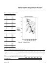
In this selection, if the return motor
BHP is equal to the exhaust motor
BHP, 21.44 BHP = 58.1 MBH x 1000÷
(1.085 x 36000 Return CFM) = 1.5°F
added to the return air temperature.
Where altitudes are significantly
above sea level, use Table 6, p. 37,
Table 7, p. 37 and Table 8, p. 37 for
applicable correction factors.
Unit Electrical Requirements
Selection procedures for electrical
requirements for wire sizing amps,
maximum fuse sizing, and dual
element fuses are given in the
electrical service section of this
catalog.
Altitude Corrections
The air handler performance tables
and curves of this catalog are based
on standard air (.075 lbs/ft). If the
airflow requirements are at other
than standard conditions (sea level),
an air density correction is needed to
project accurate unit performance.
Figure 18, p. 37 shows the air density
ratio at various temperatures and
elevations.
The procedure to use when selecting
a supply or exhaust/return fan at
elevations and
temperatures other than standard is
as follows:
1. First, determine the air density
ratio using Figure 18, p. 37.
2. Divide the static pressure at the
nonstandard condition by the air
density ratio to obtain the
corrected static pressure.
3. Use the actual CFM and the
corrected static pressure to
determine the fan RPM and BHP
from the performance tables or
curves.
4. The fan RPM is correct as
selected.
5. BHP must be multiplied by the
air density ratio to obtain the
actual operating BHP.
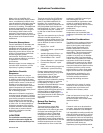
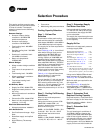
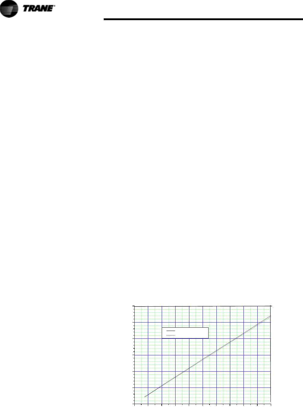
Figure 17. Fan Motor Heat
0 102030405060708090100
0
50
100
150
200
250
300
PM1206
FAN MOTOR HEAT
Std Motor
Hi Efficiency Motor
Fan Motor Heat MBH
Motor Brake Horse Power
In order to better illustrate this
procedure, the following example is
used:
Consider an air handler"C" that is to
deliver 32000 actual CFM at 3-inches
total static pressure (tsp), 55°F
leaving air temperature, at an
elevation of 5000 ft.
1. From Figure 18, p. 37, the air
density ratio is 0.86.
2. Tsp = 3.0-inches / 0.86 = 3.49
inches tsp.
3. From fan performance Table 17,
p. 48 air handler"C" (without inlet
vanes) will deliver 32000 CFM at
3.49 inches TSP at 997 RPM and
30.27 BHP.
4. The RPM is correct as selected -
997 RPM.
5. BHP = 30.27 x 0.86 = 26.3 BHP
actual.
Cooling coil MBH should be
calculated at standard and then
converted to actual using the
correction factors in Table 6, p. 37,
Table 7, p. 37, Table 8, p. 37. Apply
these factors to the capacities
selected at standard CFM so as to
correct for the reduced mass flow
rate across the condenser.
Heat selections other than gas heat
will not be affected by altitude.
Nominal gas capacity (output) should
be multiplied by the factors given in
Table 8, p. 37 before calculating the
heating supply air temperature.