


Dual Servo Spin Welder User’s Manual
Dukane Manual Part No. 403-570-01Page 98
Pin Signal Description Function
1 Top-Of-Stroke Status Output ON when press is at Top-of-Stroke position
2 Vacuum On Output, Part Pickup ON when welder calls for vacuum to be turned ON with Part Pickup mode
enabled
3 Bad Part Status Output ON when weld process is outside dened limits with Bad option enabled
4 Suspect Part Status Output ON when weld process is outside dened limits with Suspect option enabled
5 Vacuum On Output, No Part
Pickup
ON when welder calls for vacuum to be turned ON with Part Pickup mode
disabled
(signal is deactivated if idle time between cycles is more than 5 minutes; one of
the RUN SWITCHES must be turned on to reactivate signal)
6 Ready Status Output ON when welder is ready to initiate a weld cycle
7 Output Common Output Common connection
8 Fixture Clamp 1 (Right) Output Function depends on conguration:
Without slide or In/Out slide: ON at start of cycle; OFF at end of cycle
With Left/Right slide: ON at start of cycle when slide is commanded to move to
In (Right) position; OFF at the end of cycle.
9 Fixture Clamp 2 (Left) Output Function depends on conguration:
Without slide or In/Out slide: not used
With Left/Right slide: ON at start of cycle when slide is commanded to move to
Out (Left) position; OFF at the end of cycle
10 Spare Output 2 Not Used
11 Spare Output 3 Not Used
12 Vacuum On Sense Input Activate when sufcient vacuum in upper tool has been detected
13 Automation Start Input Activate to initiate a weld cycle (500 ms min.) with Start Type set to Automation
14 Input Common Input Common Connection
15 Spare Input 1 Not Used
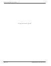
5 4 3 2 1
6
10
15 14 13 12 11
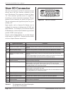
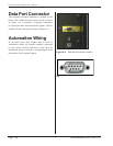
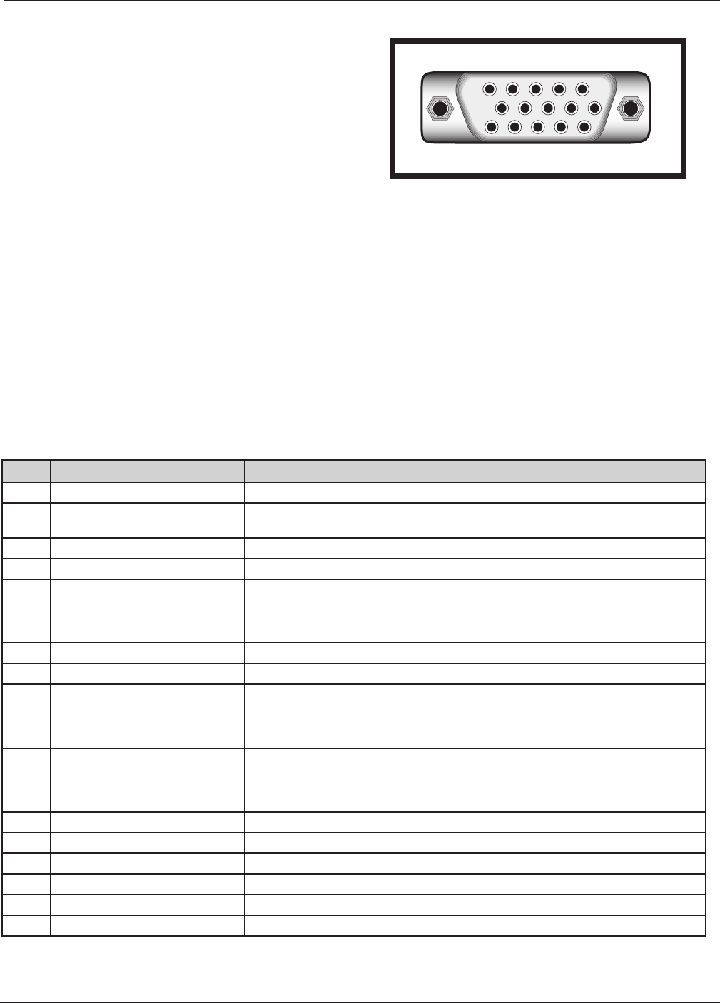
User I/O Connector
The User I/O connector is a HD–15 connector located
directly above the base interface connector on the
rear of the thruster. The connector is shown in Figure
3–8. This connector provides access to signals for
interfacing to custom automation equipment. The pin
numbers for the connector are shown in Figure A–2.
The pin assignments and signal descriptions are given
in Table A-II.
Input signals, such as Vacuum On Sense, can be
congured as sourcing or sinking using 24 VDC and
Input Common. For example, to activate the Vacuum
On Sense input, connect Input Common to ground and
provide 24VDC on the input pin.
Outputs, such as Ready Status, are provided through
relays rated at 1A@24VDC. Outputs provide contact
closure to Output Common when active.
Table A-II Pin Assignments and Signal Description
for the User I/O Connector
Figure A–2 User I/O Connector