


Dukane Manual Part No. 403-570-01
Page 69
Section 8 - Welder Data Export Software
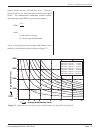
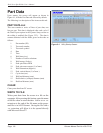
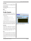
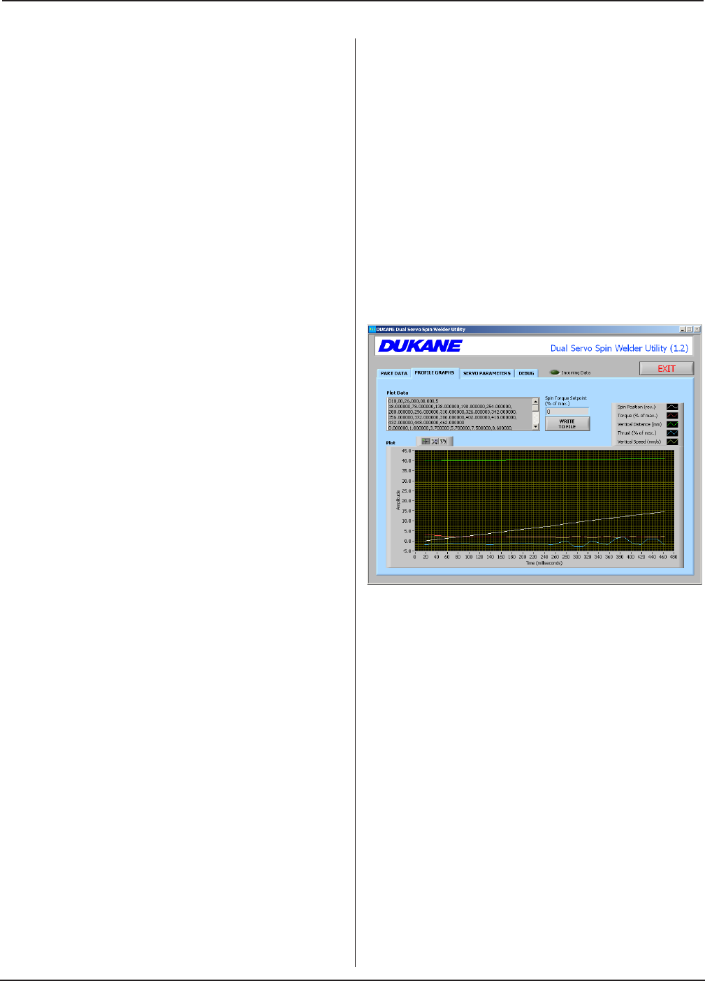
Figure 8–2 PROFILE GRAPHS Tab
File Write
Sets the write behavior for an existing le. Write Over
overwrites an existing le, while Add On appends data
to the end of the le.
Incoming Data
This indicator will ash when data is being received
from the welder.
EXIT
Exits program.
Prole Graphs
The
PROFILE GRAPHS
tab, shown in Figure 8-2,
contains numerical and graphical representations of the
following weld parameter proles with respect to time
for the last cycle:
1. Spin Position (rev.)
2. Torque (% of max.) - spin motor torque
3. Vertical Distance (mm)
4. Thrust (% of max.) - vertical actuator thrust
5. Vertical Speed (mm/s)
This data is exported by the welder after each cycle if
the Graph Export option in the System Setup screen is
enabled (see Figure 5-32). It can also be exported on
demand by pressing the
EXPORT LAST WELD GRAPH
DATA
button in the Utilities screen (see Figure 5-30).
Plot Data
The prole data is displayed in this box with comma-
separated values. The rst line is a header row,
containing the following parameters: total number of
samples, sampling rate prior to trigger (ms), sampling
rate during weld (ms), sample number at which weld
started, torque trigger setting (% of max. / 10).
Plot
The plot shows all the prole curves (vertical axis)
with respect to time (horizontal axis) in milliseconds.
The icons immediately above the plot contain tools
for a more detailed examination of the plot. Both the
horizontal and vertical scale end values can be changed
by double-clicking on the desired number and entering
a new value.