


Dukane Manual Part No. 403-570-01
Page 31
Section 5 - Touch Screen Menus
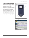
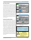
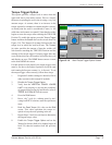
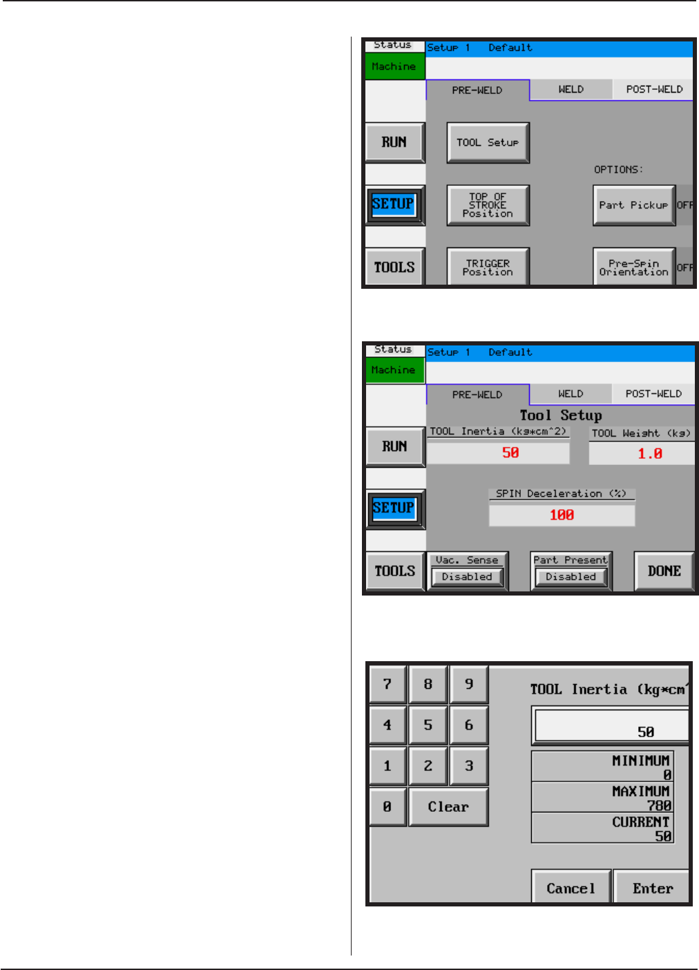
Figure 5–6 Sample Data Entry Screen
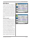
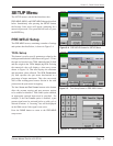
SETUP Menu
The SETUP menu is sub-divided into three tabs:
PRE-WELD, WELD, and POST-WELD that are described
below. Immediately after pressing the SETUP button,
the Security Code screen will appear, prompting for a
numerical password. If no password has been set, press
the ENTER key.
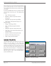
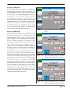
PRE-WELD Setup
The PRE-WELD screen, containing a number of settings
and options described below, is shown in Figure 5-4.
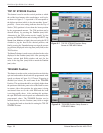
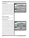
TOOL Setup
This button is used to specify parameters related to the
tooling assembled to the welder shown in Figure 5-5. Enter
the spin tool inertia in the TOOL Inertia (kg*cm^2) eld
and the weight in the TOOL Weight (kg) eld. Pressing
the numerical value cell displays a data entry screen
shown in Figure 5-6. That also displays the minimum
and maximum values allowed. The SPIN Deceleration
(%) eld species the spin motor deceleration as a
percentage of motor maximum. This value can exceed
100% when welding parts because friction in the weld
joint assists the spin motor in stopping.
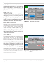
The Vac. Sense and Part Present buttons at the bottom
allow the vacuum sensing and part presence options
to be enabled or disabled. With either option enabled,
an appropriate external input must be provided. For
example, if the Part Present option is enabled, a part
present signal must be activated before a weld cycle is
allowed to initiate. A “frowning” face will be displayed
on the RUN screen if this signal is not active.
Press the DONE button to return to the PRE-WELD
setup screen.
Figure 5–4 PRE-WELD Screen for SETUP Menu
Figure 5–5 Tool Setup Screen in PRE-WELD Menu