


Dukane Manual Part No. 403-570-01
Page 43
Section 5 - Touch Screen Menus
eld designates the position of the thruster (part of the
welder surrounded by sheet metal covers) relative to
the column as indicated by the scale afxed to the right
side of the column and a white line printed on the rear
of the welder. Once these settings are entered, pressing
the DONE button causes a return to the main UTILITIES
screen, where a yellow SAVE OTHER SETTINGS button
appears. Press this button, then Save and DONE on the
following screen to retain the settings in memory.
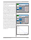
The EXPORT LAST WELD GRAPH DATA button
is used to send weld prole data information for the
last cycle to an externally connected computer via the
Dual Servo Spin Welder Utility (refer to Chapter 8).
This data includes the spin torque, spin orientation,
vertical thrust, vertical position, and vertical speed. It
is displayed in graphical format in the Utility and can
be exported to an ASCII le.
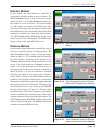
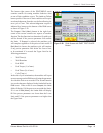
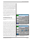
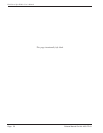
SYSTEM SETUP Tab
The third tab is labeled SYSTEM SETUP and is shown
in Figure 5-32.
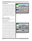
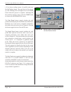
The welder contains an assembly used to limit the
downward travel of the press to prevent tooling
from coming in contact. This assembly consists of
a mechanical stop block with an integral proximity
switch, whose position is adjusted via an elevator
screw driven by a small DC motor. If, during normal
operation, the press travels down and the proximity
switch becomes active, the press motion will quickly
decelerate to a stop. The actual physical hard stop is
approximately 4 mm below this position since the
stop block includes a cushion to protect the vertical
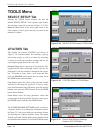
servo actuator from damaging impact loads. To set the
lower limit proximity switch position, rst press the
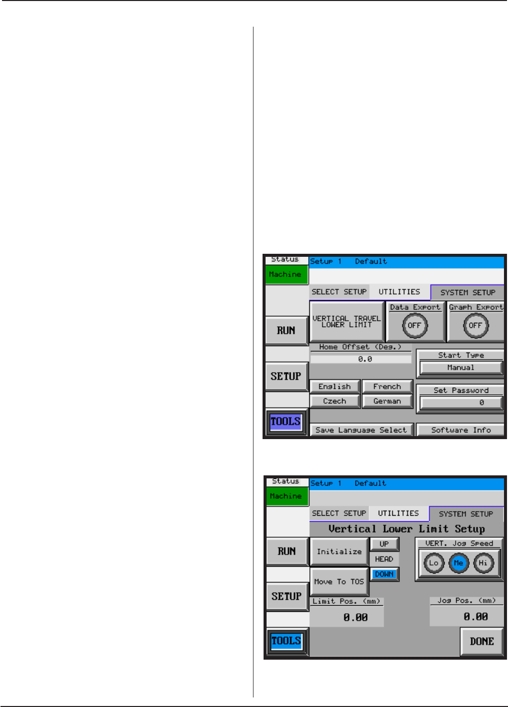
VERTICAL TRAVEL LOWER LIMIT button. Then press
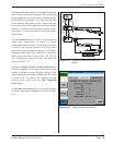
the Initialize button shown on the screen in Figure 5-33,
which will cause the stop block to move all the way
down, which takes 1 minute as indicated by a ashing
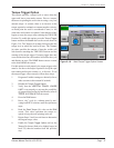
message. When this step is completed, the screen will
change as indicated in Figure 5-34. Next, jog the head
down to the desired travel limit position (at least 4 mm
Figure 5–32 SYSTEM SETUP Tab in TOOLS
Figure 5–33 Vertical Lower Limit Setup Screen
with Initialize Button