


Dual Servo Spin Welder User’s Manual
Dukane Manual Part No. 403-570-01Page 16
WARNING
DO NOT LIFT the Dual Ser-
vo Spin Welder manually.
Lifting and/or moving the
welder manually could re-
sult in personal injury. Use
mechanical means to move
and place the welder.
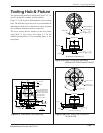
Two
1
/
2
" Holes
On 13
1
/
4
" Centers
Securing to Work
Bench
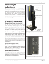
Bench Capacity
The Dual Servo Spin Welder weighs approximately 400
lbs. (182 kg). It should be attached to a table or bench
capable of supporting 650 lbs. (295 kg) to accommodate
the additional force imposed by the vertical movement of
the motor and slide during the spin welding operation.
Use mechanical means such as a forklift or hoist to
place the servo spin welder on its work bench. There are
two
3
/4 inch lifting eyes located at the top of the column
(see Figure 3–7) for a lifting ring or strap. Remove any
remaining plastic wrap after the welder is in its nal
position.
Leveling
We recommend that the Dual Servo Spin Welder be
leveled to within one degree. This can be accomplished
using a carpenter’s level. One degree corresponds to
approximately one–quarter of an inch (6 mm) deviation
across the 16 inch (406 mm) width of the platen.
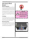
Mounting Holes
The base of the
Dual Servo
Spin Welder has two mounting
holes in the front as shown in Figure 3–1. The two holes
will accept either 12mm or 7/16” diameter bolts. We
recommend that you securely attach the welder base to
the work table using these mounting holes.
Figure 3–1 Mounting Hole Locations on Base