


Dual Servo Spin Welder User’s Manual
Dukane Manual Part No. 403-570-01Page 44
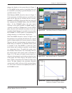
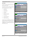
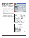
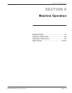
[.15 in.] above tooling contact, if possible) and press
the Set Position button. The stop block will be moved
up, and a ashing circle will appear next to the DOWN
button when this process is complete, indicating that
the proximity switch is active. Press the DONE button
to return to the SYSTEM SETUP screen.
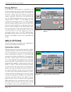
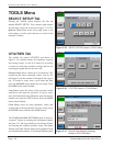
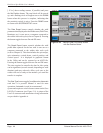
The Data Export button controls whether the weld
parameter data displayed on the RUN screen (Weld Time,
Rotations, etc.) is sent out to a computer connected to
the welder after each cycle (refer to Chapter 8). Pressing
the button toggles between On and Off states.
The Graph Export button controls whether the weld
prole data captured for the last weld is sent out to a
computer connected to the welder after each cycle
(refer to Chapter 8). This data includes the spin torque,
spin orientation, vertical thrust, vertical position, and
vertical speed. It is displayed in graphical format
in the Utility and can be exported to an ASCII le.
Pressing the button toggles between On and Off states.
The time required to transfer the data for this option
can be signicant (several seconds, depending on weld
duration) and may adversely affect cycle rate as the
welder will not be ready to run another cycle until the
transfer is complete.
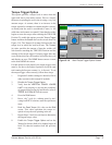
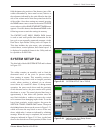
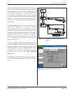
The Start Type button toggles from Manual to Automatic
each time it is pressed. Manual is used for most
operations. Automatic is used in an automated
system and requires a switch closure contact on the User
I/O HD-15 connector (see Figure 3–9). A pinout of the
User I/O connector and automation wiring information
are provided in Appendix A.
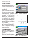
Figure 5–34 Vertical Lower Limit Setup Screen
with Set Position Button