


“C” Group: Intelligent Terminal Functions
Configuring
Drive Parameters
3–36
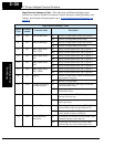
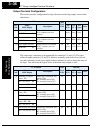
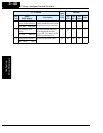
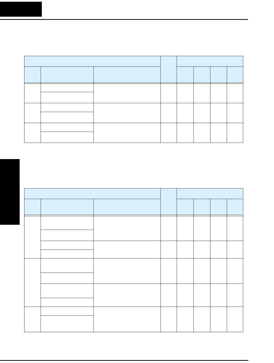
Output Terminal Configuration
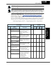
The inverter provides configuration for logic (discrete) and analog outputs, shown in the
table below.
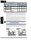
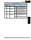
The output logic convention is programmable for terminals [11] and [12]. The open-
collector output terminals [11] and [12] default to normally open (active low), but you
can select normally closed (active high) for these terminals in order to invert the sense of
the logic. You can invert the logical sense of the alarm relay output as well.
“C” Function
Run
Mode
Edit
Defaults
Func.
Code
Name /
SRW Display
Description
–FE
(CE)
–FU
(UL)
–FR
(Jpn)
Units
C_21 Terminal [11] function Select function for terminal
[11], 6 options (see next
section)
✘
01
[FA1]
01
[FA1]
01
[FA1]
—
OUT-TM 1 FA1
C_22 Terminal [12] function Select function f or terminal
[12], 6 options (see next
section)
✘
00
[RUN]
00
[RUN]
00
[RUN]
—
OUT-TM 2 RUN
C_23 [FM] signal selection Select function for terminal
[FM], 3 options (see next
section)
✘
00
[A–F]
00
[A–F]
00
[A–F]
—
MONITOR A-F
“C” Function
Run
Mode
Edit
Defaults
Func.
Code
Name /
SRW Display
Description
–FE
(CE)
–FU
(UL)
–FR
(Jpn)
Units
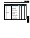
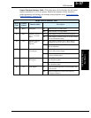
C_31 Terminal [11] active
state (–FU)
Select logic convention, two
option codes:
00 ...normally open [NO]
01 ...normally closed [NC]
✘ —00——
OUT-TM O/C-1 NO
Reserved (–FE / –FR) (reserved) DO NOT EDIT ✘ 00 — 00 —
(not displayed)
C_32 Terminal [12] active
state (–FU)
Select logic convention, two
option codes:
00 ...normally open [NO]
01 ...normally closed [NC]
✘ —00——
OUT-TM O/C-2 NO
Terminal [11] active
state (–FE / –FR)
(reserved) DO NOT EDIT ✘ 00 — 00 —
OUT-TM O/C-1 NO
C_33 Alarm relay active state Select logic convention, two
option codes:
00 ...normally open [NO]
01 ...normally closed [NC]
✘ 01 01 01 —
OUT-TM O/C-RY NO