L100 Inverter
Motor Control
Accessories
5–7
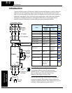
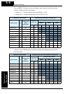
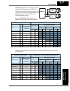
400V Class Inverters – The following tables
specify the braking options for 400V class
L100 inverters and the braking torque for each
option. You can connect a single braking unit
to the inverter, or two braking units for
additional braking torque.
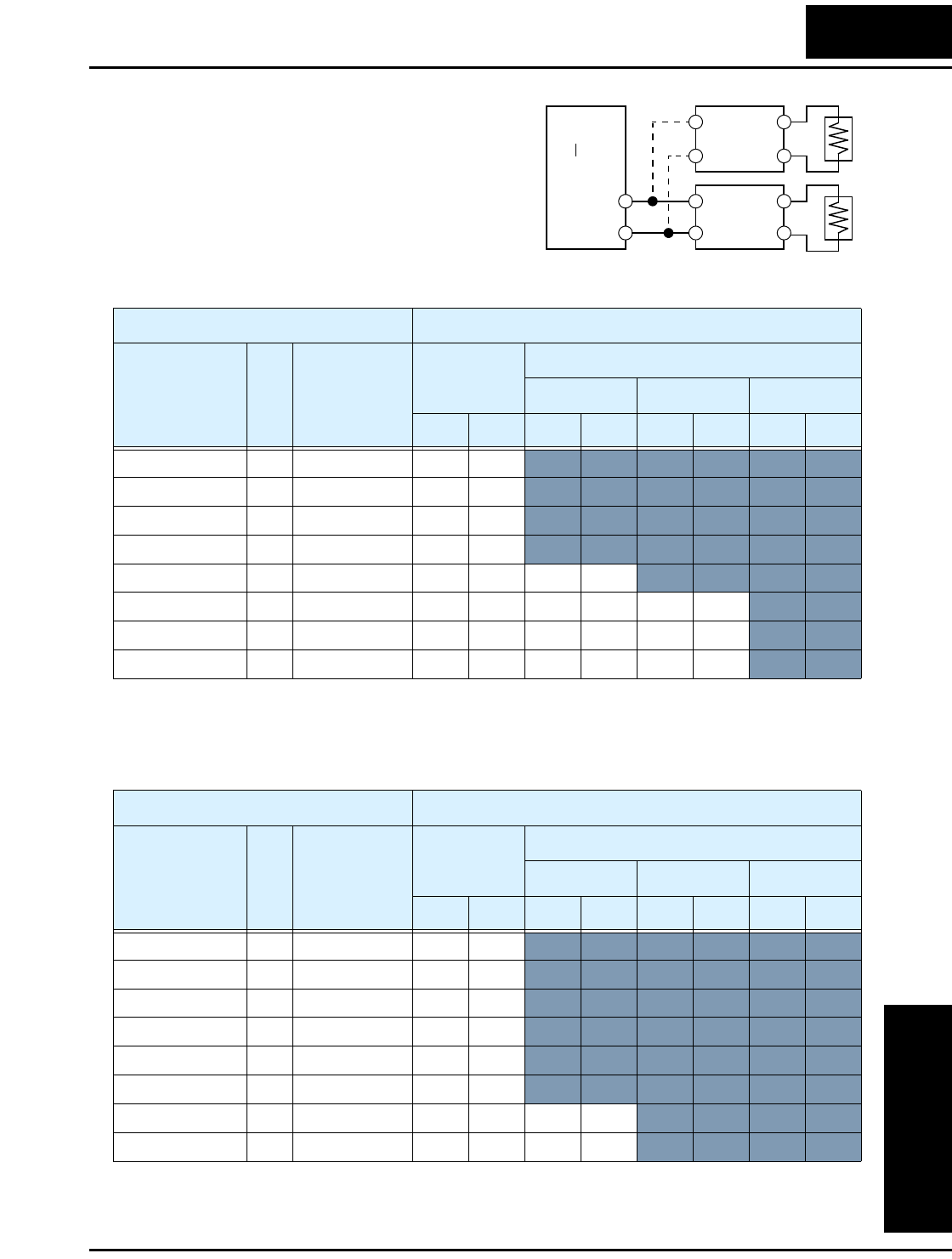
Use one BRD–EZ2 braking unit for the
braking torque listed in the following table.
Connect a second braking unit in parallel for additional braking torque listed in the
following table.
Inverter
+
–
Braking
unit
Braking
unit
L100 Inverter 400V Models Braking Torque with BRD–EZ2 Braking Unit
Model Number HP
Braking torque
without
braking unit
Using built-in
resistor only
External resistor added
HRB1 x (2) HRB2 x (2) HRB3 x (2)
A B A B A B A B
004HFE/HFU 1/2 50% 150% 150%
007HFE/HFU 1 50% 150% 150%
015HFE/HFU 2 50% 100% 100%
022HFE/HFU 3 20% 60% 60%
030HFE/HFU 4 20% 50% 50% 150% 150%
040HFE/HFU 5 20% 40% 40% 130% 130% 150% 150%
055HFE/HFU 7.5 20% 30% 30% 100% 100% 130% 130%
075HFE/HFU 10 20% 20% 20% 70% 70% 100% 100%
L100 Inverter 400V Models Braking Torque with TWO (2)BRD–EZ2 Braking Units
Model Number HP
Braking torque
without
braking unit
Using built-in
resistor only
External resistor added
HRB1 x (2) HRB2 x (2) HRB3 x (2)
A B A B A B A B
004HFE/HFU 1/2 50% 150% 150%
007HFE/HFU 1 50% 150% 150%
015HFE/HFU 2 50% 150% 150%
022HFE/HFU 3 20% 130% 130%
030HFE/HFU 4 20% 100% 100%
040HFE/HFU 5 20% 70% 70%
055HFE/HFU 7.5 20% 50% 50% 150% 150%
075HFE/HFU 10 20% 40% 40% 140% 140%


