


PID Loop Operation
Operations
and Monitoring
4–32
PID Loop Operation
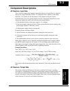
In standard operation, the inverter uses a reference source selected by parameter A_01
for the output frequency, which may be a fixed value (F_01), a variable set by the front
panel potentiometer, or value from an analog input (voltage or current). To enable PID
operation, set A_71 = 01. This causes the inverter to calculate the target frequency, or
setpoint.
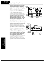
A calculated target frequency can have a lot of advantages. It lets the inverter adjust the
motor speed to optimize some other process of interest, potentially saving energy as
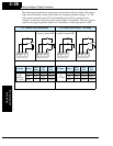
well. Refer to the figure below. The motor acts upon the external process. To control that
external process, the inverter must monitor the process variable. This requires wiring a
sensor to either the analog input terminal [O] (voltage) or terminal [OI] (current).
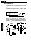
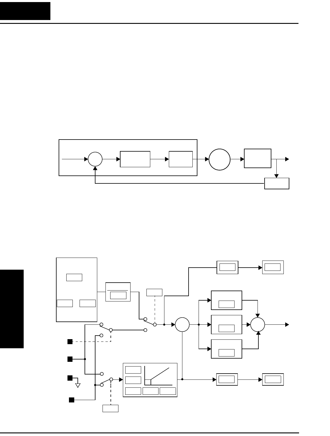
When enabled, the PID loop calculates the ideal output frequency to minimize the loop
error. This means we no longer command the inverter to run at a particular frequency,
but we specify the ideal value for the process variable. That ideal value is called the
setpoint, and is specified in the units of the external process variable. For a pump appli-
cation it may be gallons/minute, or it could be air velocity or temperature for an HVAC
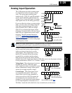
unit. Parameter A_75 is a scale factor that relates the external process variable units to
motor frequency. The figure below is a more detailed diagram of the PID function.
∑
PID
Calculation
Setpoint
SP
Error Freq.
Inverter Motor
External
Process
Process Variable (PV)
Sensor
PV
Monitor
P gain
I gain
D gain
∑
Analog input scaling
∑
Voltage
O
OI
L
Current
A GND
PID V/I input select
Process Variable
(Feedback)
Scale factor
Frequency
setting
Scale factor
Setpoint
(Target)
Scale factor
reciprocal
Multi-speed
settings
Standard
setting
Frequency
source select
Potentiometer
on keypad
Error
[AT]
V/I input
select
PV
SP
D04A75
A74
A76
A14A13A15
A12
A11
A01
F01
A20
A75
A72
A73
to
A75
1
A35
F01