


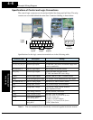

Using Intelligent Input Terminals
Operations
and Monitoring
4–10
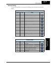
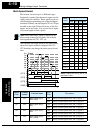
Multi-Speed Select
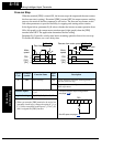
The inverter can store up to 16 different target
frequencies (speeds) that the motor output uses for
steady-state run condition. These speeds are acces-
sible through programming four of the intelligent
terminals as binary-encoded inputs CF1 to CF4 per
the table to the right. These can be any of the five
inputs, and in any order. You can use fewer inputs
if you need eight or fewer speeds.
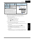
Note: When choosing a subset of speeds to use,
always start at the top of the table, and with the
least-significant bit: CF1, CF2, etc.
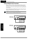
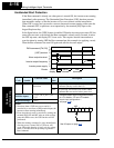
The example with eight speeds in the figure below
shows how input switches configured for CF1–
CF3 functions can change the motor speed in real
time.
NOTE: Speed 0 is set by the A_20
parameter value.
Multi-
speed
Input Function
CF4 CF3 CF2 CF1
Speed 0 0000
Speed 1 0001
Speed 2 0010
Speed 3 0011
Speed 4 0100
Speed 5 0101
Speed 6 0110
Speed 7 0111
Speed 8 1000
Speed 9 1001
Speed 101010
Speed 111011
Speed 121100
Speed 131101
Speed 141110
Speed 151111
[CF1]
[CF2]
[CF3]
[FWD]
t
Speed
0th
4th
6th
1st
2nd
5th
7th
3rd
1
0
1
0
1
0
1
0
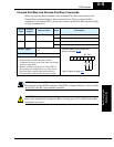
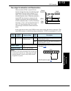
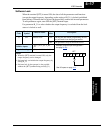
Option
Code
Terminal
Symbol
Function Name
Input
State
Description
02 CF1 Multi-speed Select,
Bit 0 (LSB)
ON Binary encoded speed select, Bit 0, logical 1
OFF Binary encoded speed select, Bit 0, logical 0
03 CF2 Multi-speed Select,
Bit 1
ON Binary encoded speed select, Bit 1, logical 1
OFF Binary encoded speed select, Bit 1, logical 0
04 CF3 Multi-speed Select,
Bit 2
ON Binary encoded speed select, Bit 2, logical 1
OFF Binary encoded speed select, Bit 2, logical 0
05 CF4 Multi-speed Select,
Bit 3 (MSB)
ON Binary encoded speed select, Bit 3, logical 1
OFF Binary encoded speed select, Bit 3, logical 0