


L100 Inverter
Index–5
Specifications
derating curves 1–11
general 1–9
inverter 1–5
label 1–4, 2–3
logic signals 4–6
Speed control 1–17, 1–21, 4–10
Speed pot 2–25
Squirrel cage A–7
Standard functions 3–9
Stator A–7
Stop command 4–9
Supply wiring 2–15
Switching frequency 3–28
Symbol definitions i
System description 2–5
T
Tachometer A–7
Technical support xviii
Term definitions A–2
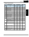
Terminal listing 4–7
Thermal overload 3–24
Thermal protection 4–20
Thermal switch A–7
Thermistor A–7
Thermistor input 4–20
Three-phase power A–7
motor phase connections 1–18
Torque 1–18, A–8
Torque boost 3–13
Torque control algorithms 3–5, 3–13
Torque specs,terminals 2–15
Transistor A–8
Trip A–8
Trip events 3–7
clearing 6–5
error codes 6–5
external 4–15
monitoring 6–5
Trip history 6–7
Trip mode 4–19
Troubleshooting tips 6–3
Two-stage accel/decel 4–13
U
UL instructions xii
Unattended start protection 4–16
Unpacking 2–2
V
V/f control 3–13
Variable torque 3–13
Variable-frequency drives
introduction 1–17
Velocity profile 1–21
Ventilation 2–8, 2–19
Voltage gain 3–14
W
Warnings
operating procedures 4–3
troubleshooting 6–2
Warranty 6–16
Watt loss A–8
Wiring
analog inputs 4–29
gauge 2–14
logic 2–18
logic connector 4–6
output 2–18
power input 2–15
preparation 2–13
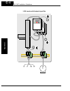
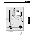
system diagram 4–5
Z
Zero-phase reactor 5–4