


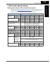

L100 Inverter Specifications
Getting Started
1–6
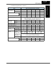
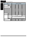
Footnotes for the preceding table and the tables that follow:
Note 1: The protection method conforms to JEM 1030.
Note 2: The applicable motor refers to Hitachi standard 3-phase motor (4-pole). When
using other motors, care must be taken to prevent the rated motor current (50/
60 Hz) from exceeding the rated output current of the inverter.
Note 3: The output voltage decreases as the main supply voltage decreases (except
when using the AVR function). In any case, the output voltage cannot exceed
the input power supply voltage.
Note 4: To operate the motor beyond 50/60 Hz, consult the motor manufacturer for
the maximum allowable rotation speed.
Note 5: The braking torque via capacitive feedback is the average deceleration torque
at the shortest deceleration (stopping from 50/60 Hz as indicated). It is not
continuous regenerative braking torque. The average deceleration torque
varies with motor loss. This value decreases when operating beyond 50 Hz.
Note that a braking unit is not included in the inverter. If a large regenerative
torque is required, the optional regenerative braking unit should be used.
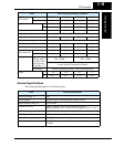
Note 6: The frequency command is the maximum frequency at 9.8V for input voltage
0 to 10 VDC, or at 19.6 mA for input current 4 to 20 mA. If this characteristic
is not satisfactory for your application, contact your Hitachi sales representa-
tive.
Note 7: If operating the inverter in an ambient temperature of 40–50
° C, reduce the
carrier frequency to 2.1 kHz, derate the output current by 80%, and remove
the top housing cover. Note that removing the top cover will nullify the
NEMA rating for the inverter housing.
Note 8: The storage temperature refers to the short-term temperature during transport.
Note 9: Conforms to the test method specified in JIS C0911 (1984). For the model
types excluded in the standard specifications, contact your Hitachi sales repre-
sentative.
Note 10: The input voltage of xxLFU is 230V.