


L100 Inverter
Configuring
Drive Parameters
3–25
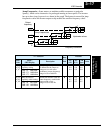
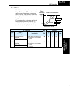
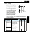
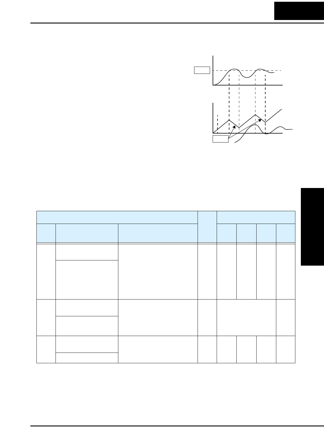
Overload Restriction
If the inverter’s output current exceeds a
preset current level you specify during
acceleration or constant speed, the overload
restriction feature automatically reduces the
output frequency to restrict the overload.
This feature does not generate an alarm or
trip event. You can instruct the inverter to
apply overload restriction only during
constant speed, thus allowing higher
currents for acceleration. Or, you may use
the same threshold for both acceleration and
constant speed. In the case of controlled
deceleration, the inverter monitors both
output current and DC bus voltage. The
inverter will increase output frequency to
try to avoid a trip due to over-current or
over-voltage (due to regeneration).
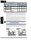
When the inverter detects an overload, it must decelerate the motor to reduce the current
until it is less than the threshold. You can choose the rate of deceleration that the inverter
uses to lower the output current.
Motor
Current
Output
frequency
B22
B23
t
t
Restriction area
0
0
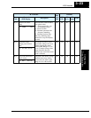
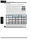
“B” Function
Run
Mode
Edit
Defaults
Func.
Code
Name /
SRW Display
Description
–FE
(CE)
–FU
(UL)
–FR
(Jpn)
Units
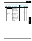
B_21 Overload restriction
operation mode
Select the operating mode
during overload conditions,
three options, option codes:
00 ...Disabled
01 ...Enabled for acceleration
and constant speed
02 ...Enabled for constant
speed only
✘ 01 01 01 —
OLOAD MODE ON
B_22 Overload restriction
setting
Sets the level for overload
restriction, between 50% and
150% of the rated current of
the inverter, setting resolution
is 1% of rated current
✘ Rated current x 1.25 A
OLOAD LVL 03.75A
B_23 Deceleration rate at
overload restriction
Sets the deceleration rate when
inverter detects overload, range
is 0.1 to 30.0, resolution is 0.1.
✘ 1.0 1.0 1.0 —
OLOAD CONST 01.0