


L100 Inverter
Inverter Mounting
and Installation
2–23
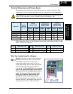
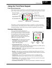
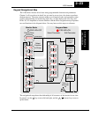
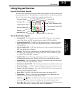
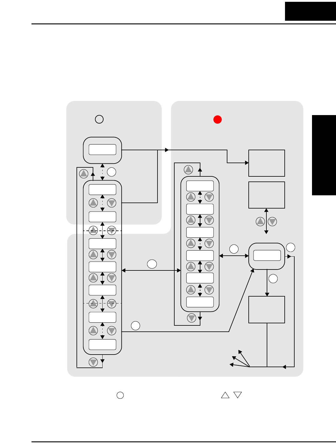
Keypad Navigational Map
The L100 Series inverter drives have many programmable functions and parameters.
Chapter 3 will cover these in detail, but you need to access just a few items to perform
the powerup test. The menu structure makes use of function codes and parameter codes
to allow programming and monitoring with only a 4-digit display and a few keys and
LEDs. So, it is important to become familiar with the basic navigational map of parame-
ters and functions in the diagram below. You may later use this map as a reference.
The navigational map shows the relationship of all resources of the inverter in one view.
In general, use the key to move left and right, and the (arrow) keys to move
up and down.
1
2
2
1
Edit
Write
data to
EEPROM
Increment/
decrement
value
2
1
2
1
2
1
2
1
2
1
1
Select Parameter
2
Return to
parameter
list
2
1
2
1
2
1
2
1
2
1
Edit Parameter
FUNC.
FUNC.
FUNC.
FUNC.
FUNC.
STR
000.0
d 09
d 01
C - -
b --
A - -
F 0 4
F 0 1
A 0 1
A 9 8
b 01
C 9 1
b 92
C 0 1
123.4
2
1
PRG LED=ONPRG LED=OFF
Program ModeMonitor Mode
Select
Function
or Group
powerdown
Store as
powerup
default
Display Data
FUNC.
1
2