


L100 Inverter
Configuring
Drive Parameters
3–39
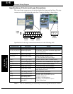
Output Function Adjustment Parameters
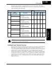
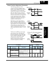
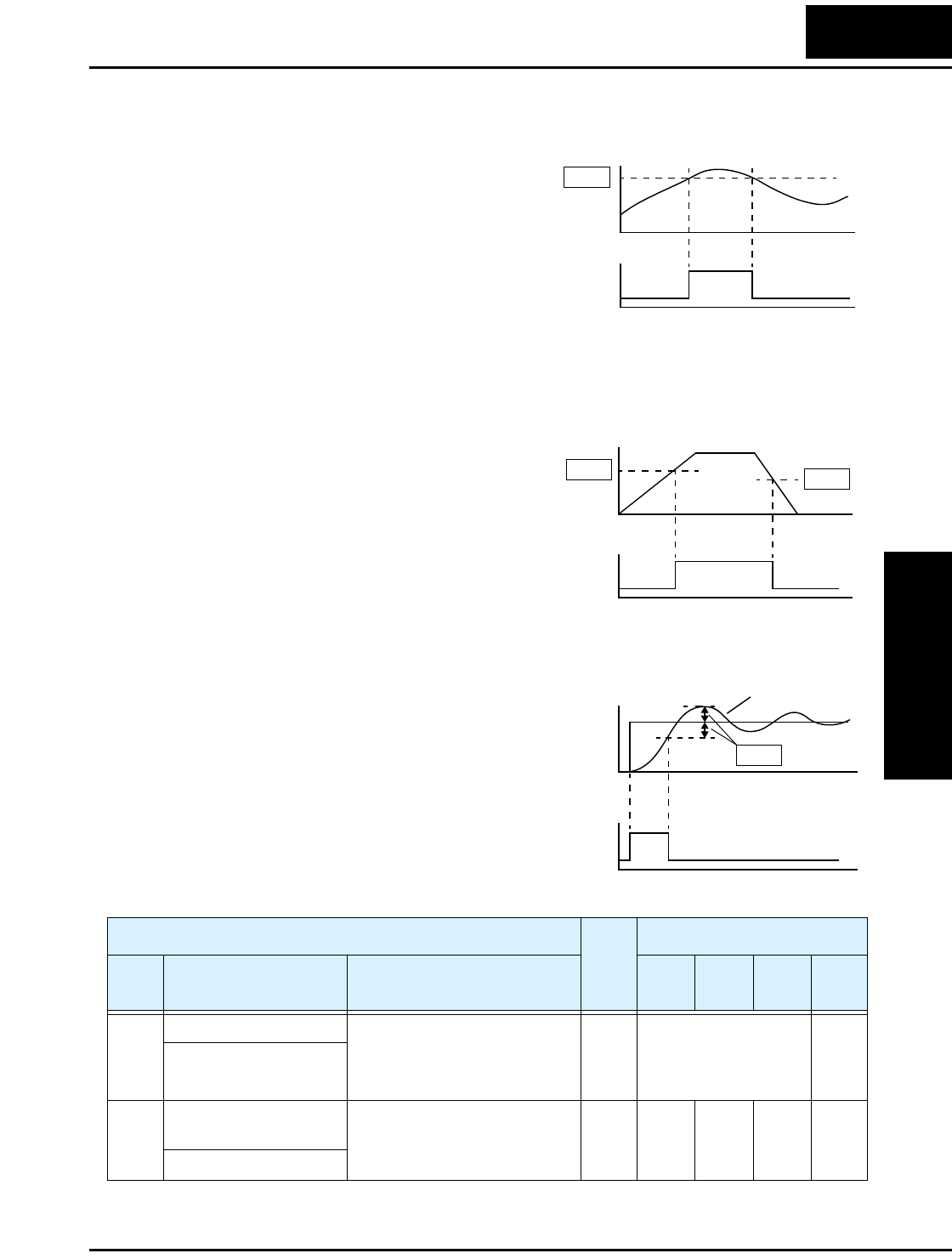
The following parameters work in
conjunction with the intelligent output
function, when configured. The overload
level parameter (C_41) sets the motor
current level at which the overload signal
[OL] turns ON. The range of settings is
from 0% to 200% of the rated current for
the inverter. This function is for generating
an early warning logic output, without
causing either a trip event or a restriction
of the motor current (those effects are
available on other functions).
The frequency arrival signal, [FA1] or
[FA2], is intended to indicate when the
inverter output has reached (arrived at) the
target frequency. You can adjust the timing
of the leading and trailing edges of the
signal via two parameters specific to accel-
eration and deceleration ramps, C_42 and
C_43.
The Error for the PID loop is the magni-
tude (absolute value) of the difference
between the Setpoint (desired value) and
Process Variable (actual value). The PID
output deviation signal [OD] (output
terminal function option code 04)
indicates when the error magnitude has
exceeded a magnitude you define.
Motor current
Overload
signal
C41
t
t
0
1
0
Output
frequency
Arrival
signal
C43
C42
t
t
0
1
0
PID Error (PV–SP) deviation threshold
Devia-
tion sig-
C44
t
t
SP
Output
PV
0
1
0
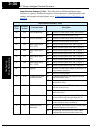
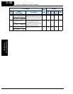
“C” Function
Run
Mode
Edit
Defaults
Func.
Code
Name /
SRW Display
Description
–FE
(CE)
–FU
(UL)
–FR
(Jpn)
Units
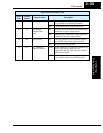
C_41 Overload level setting Sets the overload signal level
between 0% and 200% (from 0
to two times the rated current
of the inverter)
✘ Rated current for each
inverter
—
OV Load 03.00A
C_42 Frequency arrival
setting for acceleration
Sets the frequency arrival
setting threshold for the output
frequency during acceleration
✘ 0.0 0.0 0.0 Hz
ARV ACC 000.0Hz