xiv
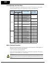
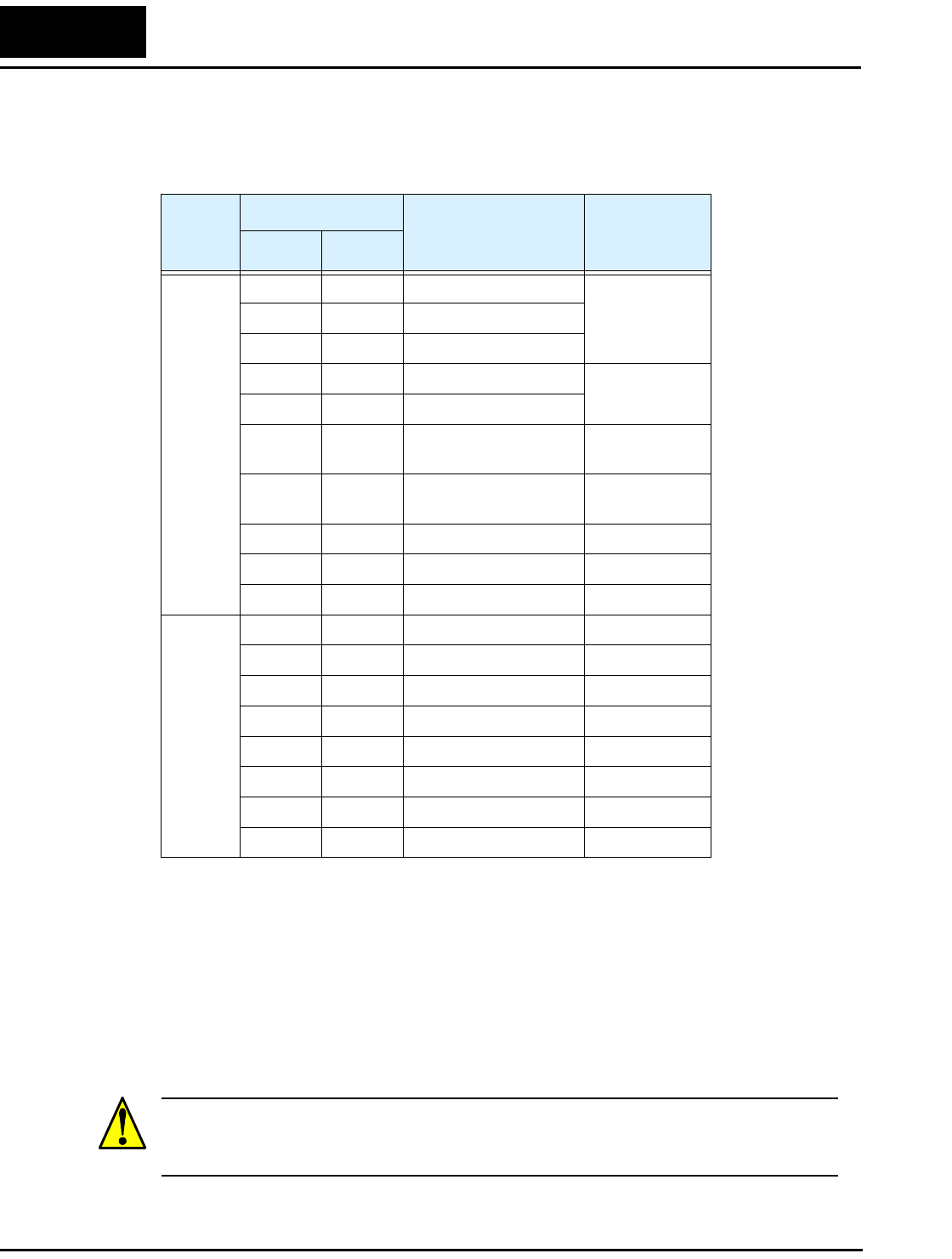
Circuit Breaker and Fuse Sizes
The inverter’s connections to input power must include UL Listed inverse time circuit
breakers with 600V rating, or UL Listed fuses as shown in the table below.
Motor Overload Protection
Hitachi L100 inverters provide solid state motor overload protection, which depends on
the proper setting of the following parameters:
• B_12 “electronic overload protection”
Set the rated current [Amperes] of the motor(s) with the above parameters. The setting
range is 0.5 * rated current to 1.2 * rated current.
WARNING: When two or more motors are connected to the inverter, they cannot be
protected by the electronic overload protection. Install an external thermal relay on each
motor.
Input
Voltage
Motor Output
Inverter Model
Fuse (A)
(UL-rated,
class J, 600V)
kW HP
200V
0.2 1/4 L100-002NFE/NFU 10 (single ph.)
7 (three ph.)
0.4 1/2 L100-004NFE/NFU
0.55 3/4 L100-005NFE
0.75 1 L100-007NFE/NFU 15 (single ph.)
10 (three ph.)
1.1 1 1/2 L100-011NFE
1.5 2 L100-015NFE/NFU 20 (single ph.)
15 (three ph.)
2.2 3 L100-022NFE/NFU 30 (single ph.)
20 (three ph.)
3.7 5 L100-037LFU 30
5.5 7 1/2 L100-055LFU 40
7.5 10 L100-075LFU 50
400V
0.4 1/2 L100-004HFE/HFU 3
0.75 1 L100-007HFE/HFU 6
1.5 2 L100-015HFE/HFU 10
2.2 3 L100-022HFE/HFU 10
3.0 4 L100-030HFE 15
4.0 5 L100-040HFE/HFU 15
5.5 7 1/2 L100-055HFE/HFU 20
7.5 10 L100-075HFE/HFU 25


