


“A” Group: Standard Functions
Configuring
Drive Parameters
3–20
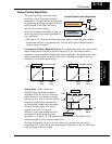
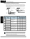
Second Acceleration and Deceleration Functions
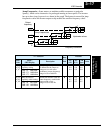
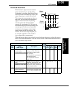
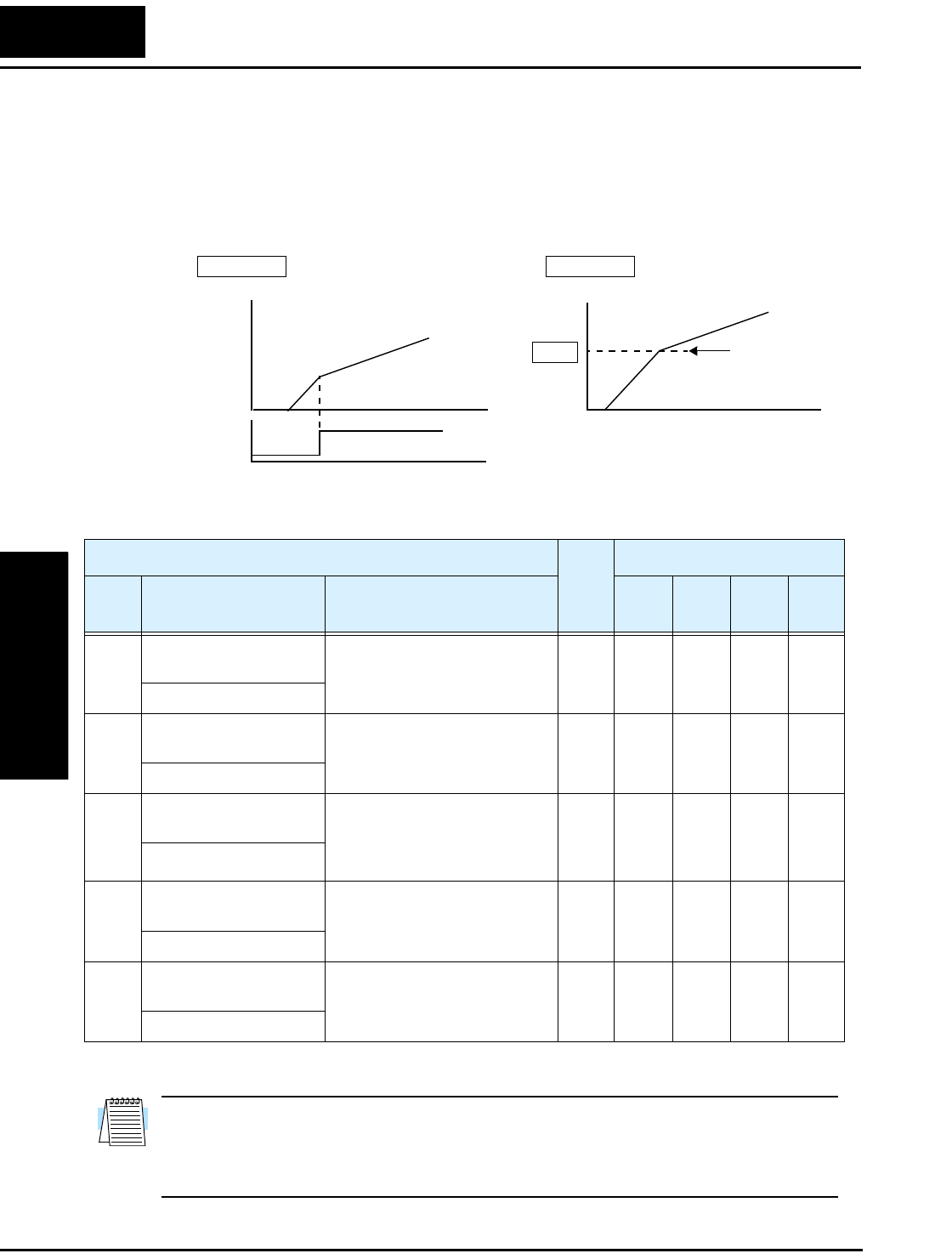
The L100 inverter features two-stage acceleration and deceleration ramps. This gives
flexibility in the profile shape. You can specify the frequency transition point, the point
at which the standard acceleration (F_02) or deceleration (F_03) changes to the second
acceleration (A_92) or deceleration (A_93). Select a transition frequency method via
A_94 as depicted below.
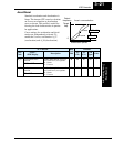
NOTE: For A_95 and A_96, if you set a very rapid Acc1 or Dec1 time (less than 1.0
second), the inverter may not be able to change rates to Acc2 or Dec2 before reaching
the target frequency. In that case, the inverter decreases the rate of Acc1 or Dec1 in order
to achieve the second ramp to the target frequency.
Accel 1
Accel 2
2CH
input
Frequency
transition point
A95
A_94
=
00 A_94
=
01
Output
frequency
Output
frequency
t
t
Accel 1
Accel 2
t
Transition via 2CH input Transition via freq. level
00
1
0
“A” Function
Run
Mode
Edit
Defaults
Func.
Code
Name /
SRW Display
Description
–FE
(CE)
–FU
(UL)
–FR
(Jpn)
Units
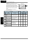
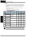
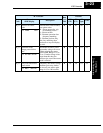
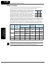
A_92 Acceleration (2) time
setting
Duration of 2nd segment of
acceleration, range is:
0.1 to 3000 sec.
✔ 15.0 15.0 15.0 sec.
ACC 2 0015.0s
A_93 Deceleration (2) time
setting
Duration of 2nd segment of
deceleration, range is:
0.1 to 3000 sec.
✔ 15.0 15.0 15.0 sec.
DEC 2 0015.0s
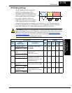
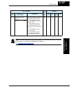
A_94 Select method to switch
to Acc2/Dec2 profile
Two options for switching
from 1st to 2nd accel/decel:
00 ...2CH input from terminal
01 ...transition frequency
✘ 00 00 00 —
ACC CHG TM
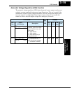
A_95 Acc1 to Acc2 frequency
transition point
Output frequency at which
Accel1 switches to Accel2,
range is 0.0 to 360.0 Hz
✘ 0.0 0.0 0.0 Hz
ACC CHFr 000.0Hz
A_96 Dec1 to Dec2 frequency
transition point
Output frequency at which
Decel1 switches to Decel2,
range is 0.0 to 360.0 Hz
✘ 0.0 0.0 0.0 Hz
DEC CHFr 000.0Hz