


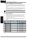
“B” Group: Fine Tuning Functions
Configuring
Drive Parameters
3–28
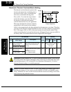
Miscellaneous Settings
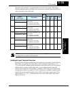
The miscellaneous settings include scaling factors, initialization modes, and others. This
section covers some of the most important settings you may need to configure.
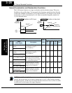
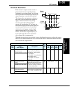
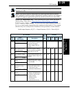
B_32: Reactive current setting – The inverter’s D_02 monitor function displays the
motor current. The display accuracy is normally ±20%, provided that the following
conditions exist:
• A single motor with standard frame size and characteristics is connected
• The inverter’s output frequency is at 50% or higher of the maximum output frequency
• The inverter’s output current is within the rated current
However, it will be necessary to calibrate the display accuracy via B_32 adjustment of
the internal no-load reactive motor current if any of these conditions exist:
• The motor is smaller than the standard maximum recommended for the inverter
• The motor is a two-pole motor type
• Two or more motors are connected in parallel to the inverter (be sure to multiply the
current by the number of motors when setting B_32)
If you do not know the reactive or no-load current for your particular motor, you can
calibrate the L100 as follows:
1. Connect the motor directly across the AC line with no load attached to the shaft.
WARNING: Use a disconnect switch or breaker to ensure that you do not connect the
motor or inverter to live wiring. Otherwise, there is the danger of electric shock.
2. Run the motor, and measure the no-load current with an AC current clamp, recording
the value.
3. Disconnect the motor from the AC line connection, and connect the motor to the
L100 inverter output (still with no load attached).
4. Run the motor at the base frequency (value of parameter A_03), and monitor the
motor current with function D_02.
5. If the D_02 display value does not match the current clamp value recorded in Step 2,
adjust parameter B_32 up or down until the best match is achieved.
NOTE: Parameter setting B_32 affects the inverter’s electronic thermal protection
(B_12 setting) and its overload restriction function (B_22 setting).
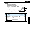
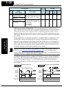
B_83: Carrier frequency adjustment – The internal switching frequency of the
inverter circuitry (also called the chopper frequency). It is called the carrier frequency
because the lower AC output frequency of the inverter “rides” the carrier. The faint,
high-pitched sound you hear when the inverter is in Run Mode is characteristic of
switching power supplies in general. The carrier frequency is adjustable from 500 Hz to
16 kHz. The audible sound decreases at the higher frequencies, but RFI noise and
leakage current may be increased. Refer to the specification derating curves in Chapter 1
to determine the maximum allowable carrier frequency setting for your particular
inverter and environmental conditions.