


L100 Inverter
Operations
and Monitoring
4–29
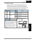
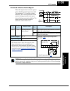
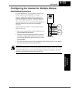
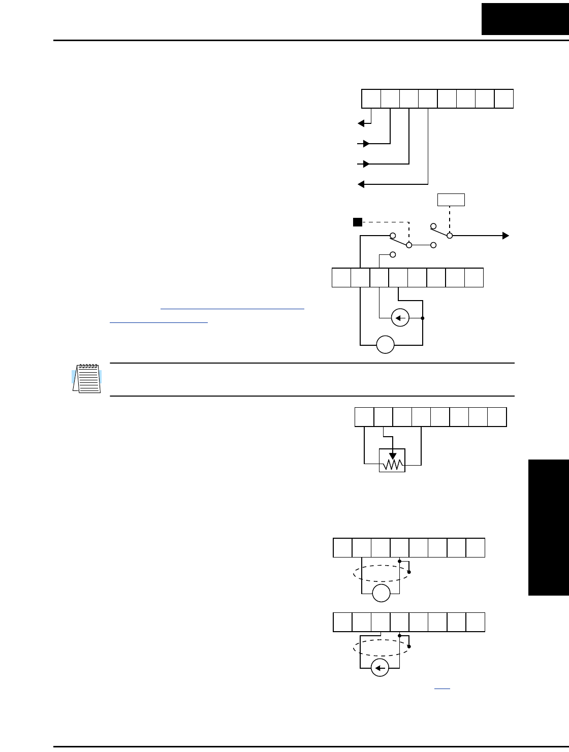
Analog Input Operation
The L100 inverters provide for analog input
to command the inverter frequency output
value. The analog input terminal group
includes the [L], [OI], [O], and [H] terminals
on the control connector, which provide for
Voltage [O] or Current [OI] input. All analog
input signals must use the analog ground [L].
If you use either the voltage or current analog
input, you must select one of them using the
logic input terminal function [AT] analog
type. If terminal [AT] is OFF, the voltage
input [O] can command the inverter output
frequency. If terminal [AT] is ON, the current
input [OI] can command the inverter output
frequency. The [AT] terminal function is
covered in “
Analog Input Current/Voltage
Select” on page 4–18. Remember that you
must also set A_01 = 01 to select analog input
as the frequency source.
NOTE: If no logic input terminal is configured for the [AT] function, then inverter sums
the voltage and current input to determine the desired input value.
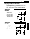
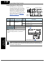
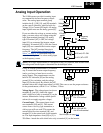
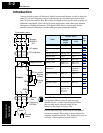
Using an external potentiometer is a common
way to control the inverter output frequency
(and a good way to learn how to use the
analog inputs). The potentiometer uses the
built-in 10V reference [H] and the analog
ground [L] for excitation, and the voltage
input [O] for the signal. By default, the [AT]
terminal selects the voltage input when it is OFF. Take care to use the proper resistance
for the potentiometer, which is 1 to 2 k Ohms, 2 Watts.
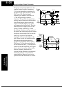
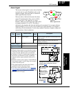
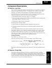
Voltage Input – The voltage input circuit uses
terminals [L] and [O]. Attach the signal
cable’s shield wire only to terminal [L] on the
inverter. Maintain the voltage within specifi-
cations (do not apply negative voltage).
Current Input – The current input circuit
uses terminals [OI] and [L]. The current
comes from a sourcing type transmitter; a
sinking type will not work! This means the
current must flow into terminal [OI], and
terminal [L] is the return back to the transmit-
ter. The input impedance from [OI] to [L] is
250 Ohms. Attach the cable shield wire only to terminal [L] on the inverter.
+V Ref.
A GND
Voltage input
Current input
12 11LH O
OI FM
CM2
+ –
4-20 mA, AT= ON
0-10 V, AT= OFF
[AT]
V/I input
select
Frequency
setting
A01
12 11LH O
OI FM
CM2
1 to 2kΩ, 2W
12 11LH O
OI FM
CM2
+ –
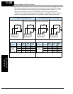
4 to 19.6 mA DC,
4 to 20 mA nominal
0 to 9.6 VDC,
0 to 10V nominal
12 11LH O
OI FM
CM2
12 11LH O
OI FM
CM2
See I/O specs on page 4–6.