


“A” Group: Standard Functions
Configuring
Drive Parameters
3–18
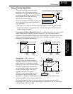
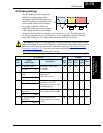
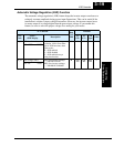
PID Control
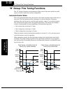
When enabled, the built-in PID loop calculates an ideal inverter output value to cause a
loop feedback process variable (PV) to move closer in value to the setpoint (SP). The
current frequency command serves as the SP. The PID loop algorithm will read the
analog input for the process variable (you specify the current or voltage input) and calcu-
late the output.
• A scale factor in A_75 lets you multiply the PV by a factor, converting it into
engineering units for the process.
• Proportional, integral, and derivative gains are all adjustable.
•See “
PID Loop Operation” on page 4–32 for more information.
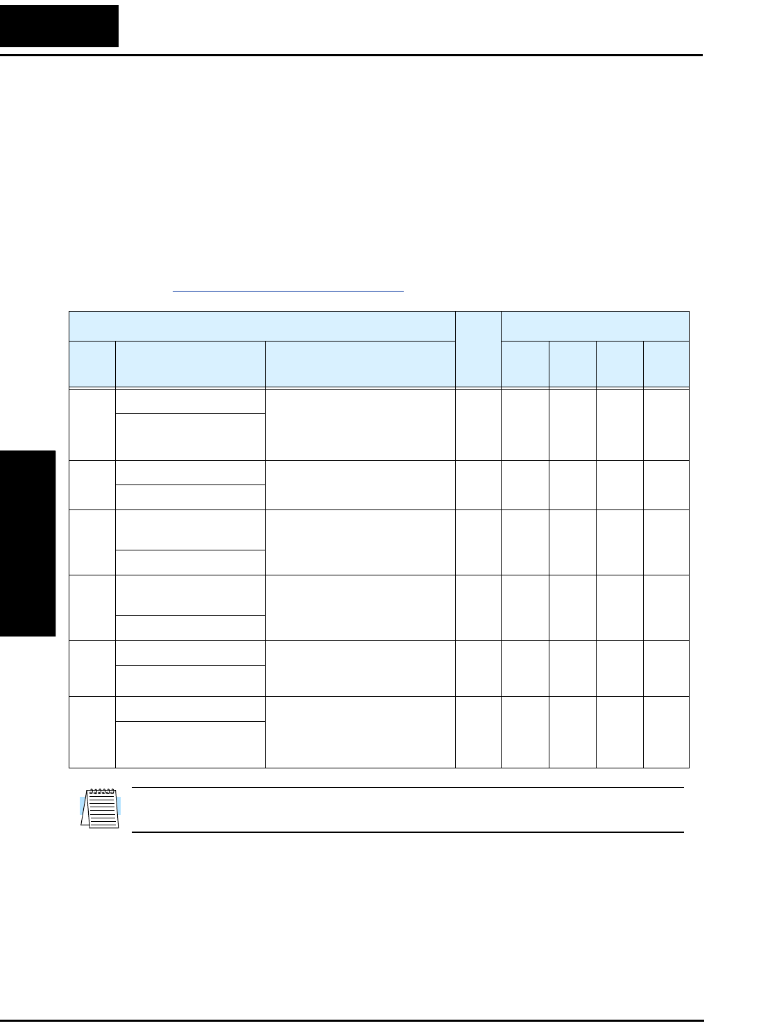
NOTE: The setting A_73 for the integrator is the integrator’s time constant Ti, not the
gain. The integrator gain Ki = 1/Ti. When you set A_73 = 0, the integrator is disabled.
“A” Function
Run
Mode
Edit
Defaults
Func.
Code
Name /
SRW Display
Description
–FE
(CE)
–FU
(UL)
–FR
(Jpn)
Units
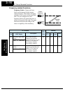
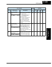
A_71 PID Enable Enables PID function,
two option codes:
00 ...PID Disable
01 ...PID Enable
✘ 00 00 00 —
PID SW OFF
A_72 PID proportional gain Proportional gain has a range
of 0.2 to 5.0
✘ 1.0 1.0 1.0 —
PID P 1.0
A_73 PID integral time
constant
Integral time constant has a
range of 0.0 to 150 seconds
✘ 1.0 1.0 1.0 sec.
PID I 001.0s
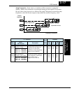
A_74 PID derivative time
constant
Derivative time constant has a
range of 0.0 to 100 seconds
✘ 0.0 0.0 0.0 sec.
PID D 00.0
A_75 PV scale conversion Process Variable (PV) scale
factor (multiplier), range of
0.01 to 99.99
✘ 1.00 1.00 1.00 —
PID CONV 01.00
A_76 PV source setting Selects source of Process
Variable (PV), option codes:
00 ...[OI] terminal (current in)
01 ...[O] terminal (voltage in)
✘ 00 00 00 —
PID INPT CUR