


INSTALLATION
A-4 A-4
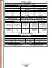
Power MIG® 215XT
3. The 208/230 volt 50/60 Hz model Power MIG® is
shipped with a 7 ft.(2.1m). input cable and plug con-
nected to the welder.
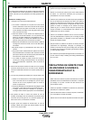
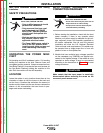
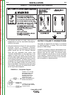
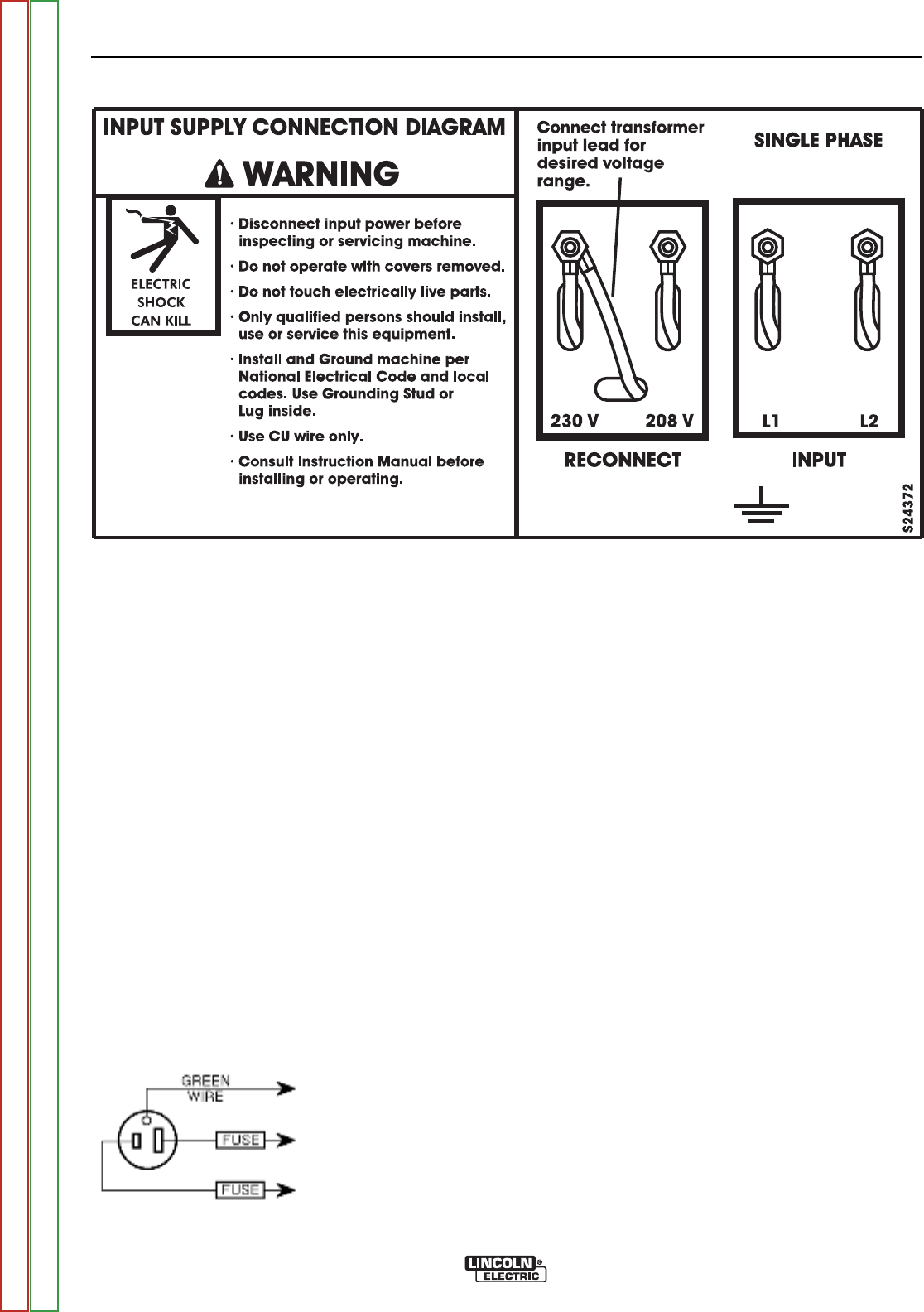
4. Using the instructions in Figure A.2, have a qualified
electrician connect a receptacle (Customer
Supplied) or cable to the input power lines and the
system ground per the U.S. National Electrical
Code and any applicable local codes. See
“Technical Specifications” at the beginning of this
chapter for proper wire sizes. For long runs over
100 feet, larger copper wires should be used. Fuse
the two hot lines with super lag type fuses as shown
in the following diagram. The center contact in the
receptacle is for the grounding connection. A green
wire in the input cable connects this contact to the
frame of the welder. This ensures proper grounding
of the welder frame when the welder plug is insert-
ed into a grounded receptacle.
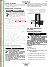
FIGURE A.2 — Receptacle Diagram
CONNECT TO A SYSTEM
GROUNDING WIRE. SEE
THE UNITED STATES
NATIONAL ELECTRICAL
CODE AND/OR LOCAL
CODES FOR OTHER
DETAILS AND MEANS FOR
PROPER GROUNDING.
CONNECT TO HOT WIRES
OF A THREE-WIRE, SINGLE
PHASE SYSTEM.
50/60 HZ
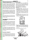
FIGURE A.1 — Dual Voltage Machine Input Connections
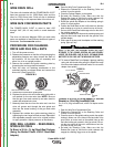
OUTPUT POLARITY CONNECTIONS
The welder, as shipped from the factory, is connected
for electrode positive (+) polarity. This is the normal
polarity for GMA welding.
If negative (–) polarity is required, interchange the con-
nection of the two cables located in the wire drive com-
partment near the front panel. The electrode cable,
which is attached to the wire drive, is to be connected
to the negative (–) labeled terminal and the work lead,
which is attached to the work clamp, is to be connect-
ed to the positive (+) labeled terminal.
Return to Section TOC Return to Section TOC Return to Section TOC Return to Section TOC
Return to Master TOC Return to Master TOC Return to Master TOC Return to Master TOC