


THEORY OF OPERATION
E-3 E-3
Power MIG® 215XT
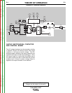
OUTPUT RECTIFICATION, CONTACTOR
AND CONTROL BOARD
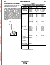
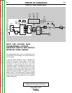
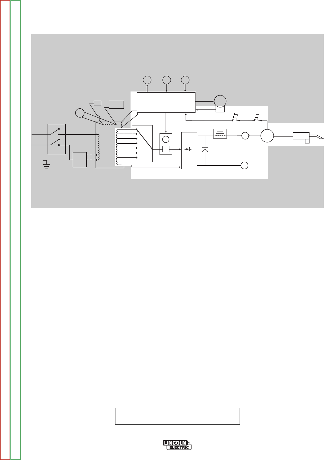
The AC voltage developed on the secondary winding
is applied, through the selector switch and output
contactor, to the output rectifier bridge. This DC
welding voltage is filtered by the output capacitors and
applied to the output terminals and welding gun. Since
the output choke is in series with the positive leg of
the output rectifier and also in series with the gun and
welding load, a filtered constant voltage output is
applied to the output terminals of the machine.
FIGURE E.2 - CONTROL CIRCUITS
LINE
SWITCH
RECONNECT
PANEL
FAN
MOTOR
CONTROL BOARD
GAS
SOLENOID
WIRE
SPEED
CONTROL
SPOOL
GUN
SWITCH
WIRE
DRIVE
MOTOR
TACH
FEEDBACK
GUN TRIGGER
+
-
OUTPUT DIODE
BRIDGE
+
-
NEGATIVE
TERMINAL
CONTACTOR
CONTACTOR
CONTROL
TAP SELECTOR
SWITCH
OUTPUT
CHOKE
POSITIVE
TERMINAL
TRANSFORMER
THERMOSTAT
OUTPUT BRIDGE
THERMOSTAT
MAIN
TRANSFORMER
OUTPUT
CAPACITORS
GUN
ASSEMBLY
115V
RECEPTACLE
CIRCUIT
BREAKER
27.8 V
AC
NOTE: Unshaded areas of Block Logic
Diagram are the subject of discussion
Return to Section TOC Return to Section TOC Return to Section TOC Return to Section TOC
Return to Master TOC Return to Master TOC Return to Master TOC Return to Master TOC