


THEORY OF OPERATION
E-2 E-2
Power MIG® 215XT
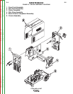
INPUT LINE VOLTAGE, MAIN
TRANSFORMER, VOLTAGE
SELECTOR SWITCH AND BAFFLE
MOUNTED DIODE BRIDGE
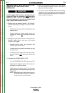
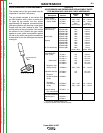
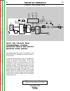
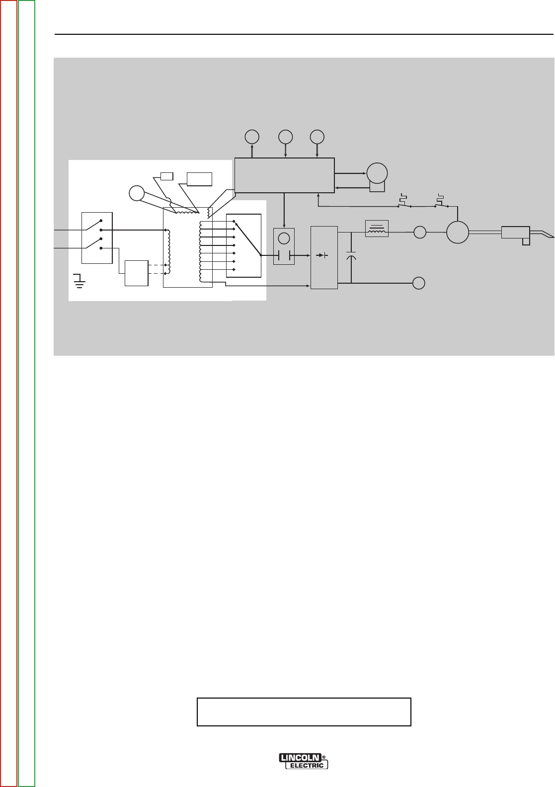
The single phase input power is connected to the
Power MIG® 215XT through a line switch located on
the front panel.
A reconnect panel allows the user to configure the
machine for the desired input voltage. The AC input
voltage is applied to the primary of the main
transformer. The cooling fan motor and 115v
receptacle (115VAC) is powered from a portion of the
secondary winding. For welding purposes, the main
transformer converts the high voltage, low current
input power to a low voltage, high current output. This
tapped secondary winding is coupled to a voltage
selector switch. By selecting one of seven positions
on the switch the user can preset the desired voltage
output from a minimum setting (A) to a maximum
voltage setting (G).
FIGURE E.2 - INPUT POWER CIRCUIT
LINE
SWITCH
RECONNECT
PANEL
FAN
MOTOR
CONTROL BOARD
GAS
SOLENOID
WIRE
SPEED
CONTROL
SPOOL
GUN
SWITCH
WIRE
DRIVE
MOTOR
TACH
FEEDBACK
GUN TRIGGER
+
-
OUTPUT DIODE
BRIDGE
+
-
NEGATIVE
TERMINAL
CONTACTOR
CONTACTOR
CONTROL
TAP SELECTOR
SWITCH
OUTPUT
CHOKE
POSITIVE
TERMINAL
TRANSFORMER
THERMOSTAT
OUTPUT BRIDGE
THERMOSTAT
MAIN
TRANSFORMER
OUTPUT
CAPACITORS
GUN
ASSEMBLY
115V
RECEPTACLE
CIRCUIT
BREAKER
27.8 V
AC
NOTE: Unshaded areas of Block Logic
Diagram are the subject of discussion
Return to Section TOC Return to Section TOC Return to Section TOC Return to Section TOC
Return to Master TOC Return to Master TOC Return to Master TOC Return to Master TOC