


OPERATION
B-7 B-7
Power MIG® 215XT
INPUT LINE VOLTAGE VARIATIONS
High Line Voltage — Higher than rated input voltage
will result in output voltages higher than normal for a
given tap setting. If your input line is high, you may
want to select a lower voltage tap than given on the
recommended procedure chart.
Low Line Voltage — You may not be able to get max-
imum output from the machine if the line voltage is less
than rated input. The unit will continue to weld, but the
output may be less than normal for a given tap setting.
If your input line is low, you may want to select a high-
er voltage tap than given on the recommended proce-
dure chart.
WIRE FEED OVERLOAD
PROTECTION
The POWER MIG® 215XT has solid state overload
protection of the wire drive motor. If the motor becomes
overloaded, the protection circuitry turns off the wire
feed speed and gas solenoid. Check for proper size tip,
liner, and drive rolls, for any obstructions or bends in
the gun cable, and any other factors that would impede
the wire feeding. to resume welding, simply pull the
trigger. There is no circuit breaker to reset, as the pro-
tection is done with reliable solid state electronics.
WELDING THERMAL OVERLOAD
PROTECTION
The POWER MIG® 215XT has built-in protective ther-
mostats that respond to excessive temperature. They
open the wire feed and welder output circuits if the
machine exceeds the maximum safe operating tem-
perature because of a frequent overload, or high ambi-
ent temperature plus overload. The thermostats auto-
matically reset when the temperature reaches a safe
operating level and welding and feeding are allowed
again, when gun is retriggered.
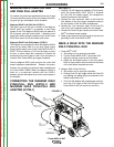
9. When no more welding is to be done, close valve on
gas cylinder (if used), momentarily operate gun trig-
ger to release gas pressure, and turn off POWER
MIG® 215XT.
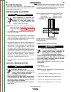
NOTE: When using Innershield electrode, the gas
nozzle may be removed from the insulation on
the end of the gun and replaced with the gas-
less nozzle. This will give improved visibility
and eliminate the possibility of the gas nozzle
overheating.
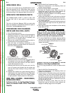
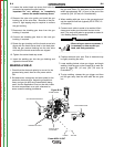
AVOIDING WIRE FEEDING
PROBLEMS
Wire feeding problems can be avoided by observing
the following gun handling procedures:
1. Do not kink or pull cable around sharp corners.
2. Keep the gun cable as straight as possible when
welding or loading electrode through cable.
3. Do not allow dolly wheels or trucks to run over
cables.
4. Keep cable clean by following maintenance instruc-
tions.
5. Use only clean, rust-free electrode. The Lincoln
electrodes have proper surface lubrication.
6. Replace contact tip when the arc starts to become
unstable or the contact tip end is fused or deformed.
7. Keep wire reel spindle brake tension to minimum
required to prevent excess reel over-travel which
may cause wire “loop-offs” from coil.
8. Use proper drive rolls and wire drive idle roll pres-
sure for wire size and type being used.
FAN CONTROL
The fan is designed to come on when input power is
applied to the POWER MIG® 215XT and go off when
power is removed.
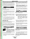
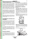
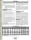
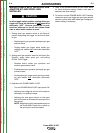
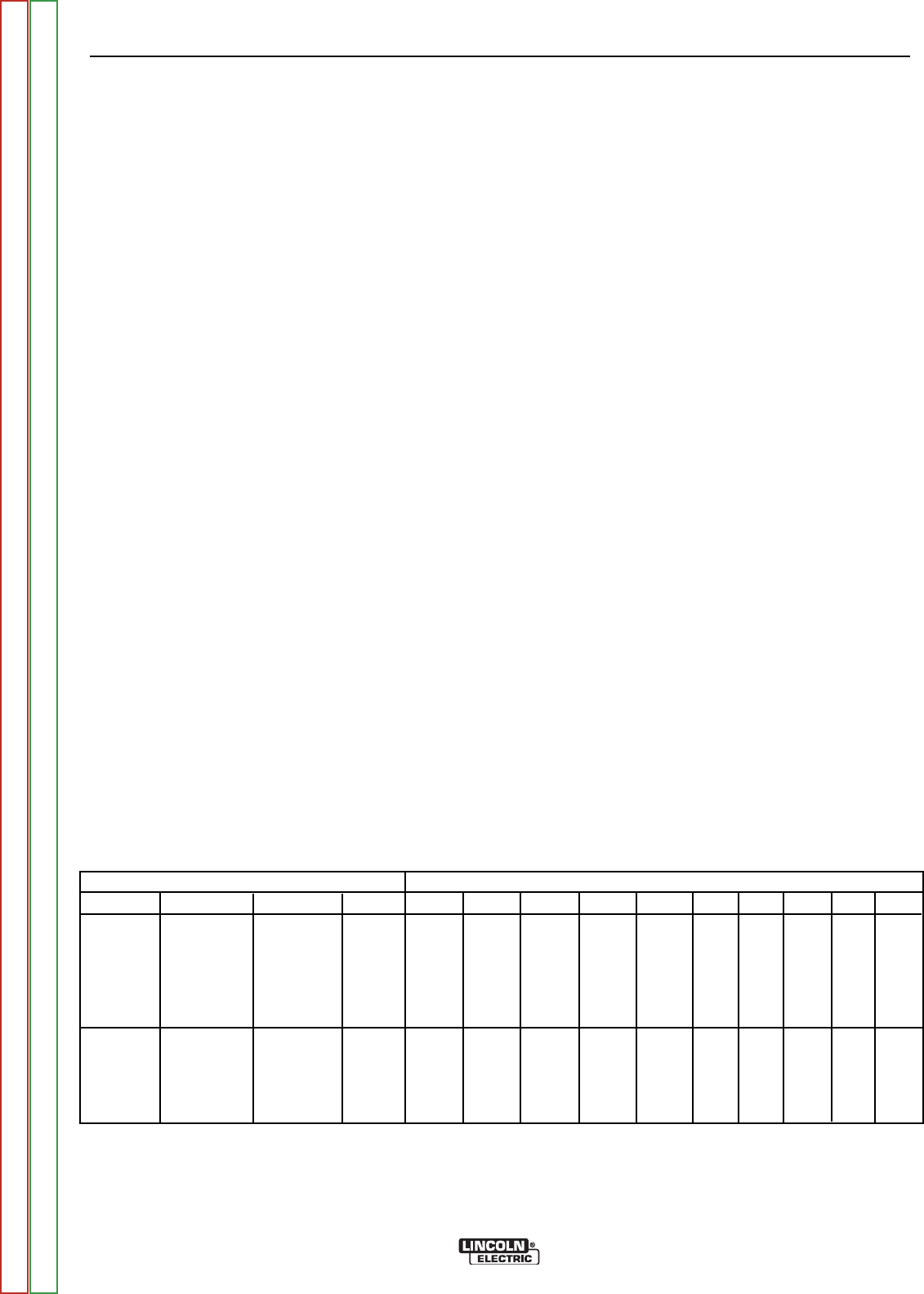
Wire Feed Speed/Voltage Tap Settings
Wire Dia. Gas Type Wire Type
Polarity 18 gage 16 gage14 gage 12 gage10gage 3/16 1/4 5/16 3/8 1/2
Outershield
1" CTWD
†
.035 75Ar/25CO
2
OS71M DC+
250/D 300/E 350/F 500/G *500/G
.035 100%CO
2
OS71M DC+
300/E 350/F 500/G
.045 75Ar/25CO
2
OS71M DC+
200/E 225/F 250/G 250/G *250/G
Innershield
5/8" CTWD
†
.035 NoneReq’d NR-211MP DC-
50/B 70/B 80/B 90/C 100/C
.045 NoneReq’d NR-211MP DC-
50/B 70/C 90/C 110/D
**130/E
.045 NoneReq’d NR212 DC-
40/B 50/B 60/B 65/C 70/C 90/C 110/D
*130/E *150/E *150/E
PROCEDURE CHART
†
Contact Tip to Work Distance
* Note- Requires Multiple Pass
**.035 & .045 NR-211 MP are only recommended for a maximum steel thickness of 5/16"
Return to Section TOC Return to Section TOC Return to Section TOC Return to Section TOC
Return to Master TOC Return to Master TOC Return to Master TOC Return to Master TOC