


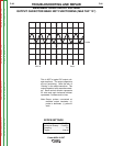
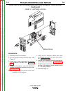
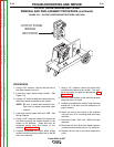

OUTPUT DIODE
BRIDGE
RECTIFIER
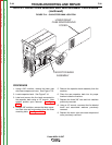
FIGURE F.12 – OUTPUT DIODE BRIDGE RECTIFIER LOCATION
OUTPUT DIODE BRIDGE RECTIFIER
REMOVAL AND REPLACEMENT PROCEDURE (continued)
PROCEDURE
1. Using a 3/8” nutdriver, remove the left side of
the case wraparound cover.
2. Locate the output diode bridge rectifier. See
Figure F.12.
3. Using a 1/2” nutdriver label and remove the four
thick black leads connected to the rectifier.
NOTE: Be sure to label lead terminals also.
Take note of washer placement upon
removal.
4. Label and remove leads 104A and 104B. See
Wiring Diagram.
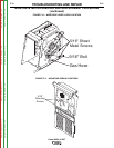
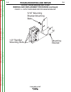
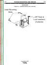
5. Using a 5/16” nutdriver locate and remove the
four bolts mounting the rectifier bracket to the
bottom of the machine. These bolts can be
accessed easily from the bottom of the
machine. See Figure F.13.
6. Carefully manipulate the output diode bridge
rectifier and the mounting bracket out of the left
side of the machine.
7. Using a 1/2” nutdriver remove the three bolts
mounting the bracket to the rectifier. The recti-
fier is now ready for repair or replacement. See
Figure F.13.
8. Mount the new rectifier to the mounting bracket
using the three 1/2” bolts.
9. Carefully manipulate the rectifier and mounting
bracket as a one back into the machine to its
proper location.
10. Mount the unit to the bottom of the machine
using the four 5/16” mounting bolts previously
removed.
11. Reconnect leads 104A and 104B previously
removed.
12. Reconnect the four thick black leads previous-
ly labeled and removed using a 1/2” nutdriver.
13. Replace the left side of the case wraparound
cover.
TROUBLESHOOTING AND REPAIR
F-34 F-34
Power MIG® 215XT
Return to Section TOC Return to Section TOC Return to Section TOC Return to Section TOC
Return to Master TOC Return to Master TOC Return to Master TOC Return to Master TOC