


OPERATION
B-6 B-6
Power MIG® 215XT
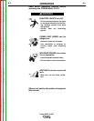
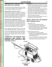
3. Press the trigger to feed the wire electrode through
the gun and cable. For solid wire cut the electrode
within approximately 3/8" (10 mm) of the end of the
contact tip [3/4" (20 mm) for Outershield
®
].
4. When welding with gas, turn on the gas supply and
set the required flow rate (typically 25-35 CFH; 12-
16 liters/min).
5. Connect work cable to metal to be welded. Work
clamp must make good electrical contact to the
work. The work must also be grounded as stated in
“Arc Welding Safety Precautions”.
• When using an open arc process, it
is necessary to use correct eye,
head, and body protection.
-----------------------------------------------------------------------
6. Position electrode over joint. End of electrode may
be lightly touching the work.
7. Lower welding helmet, close gun trigger, and begin
welding. Hold the gun so the contact tip to work dis-
tance is about 3/8" (10 mm) [3/4" (20 mm) for
Outershield
®
].
8. To stop welding, release the gun trigger and then
pull the gun away from the work after the arc goes
out.
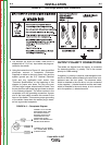
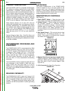
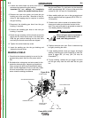
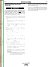
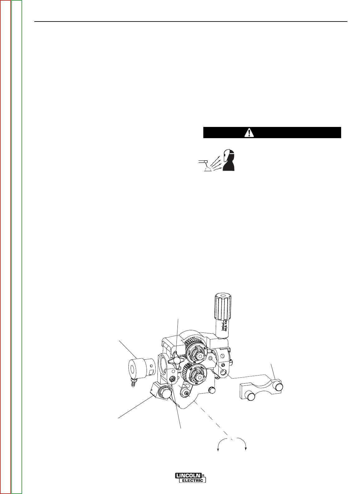
GUN RECEIVER BUSHING
LOOSEN TIGHTEN
THUMB SCREW
OUTER WIRE GUIDE
SOCKET HEAD
CAP SCREW
CONNECTOR BLOCK
5. Loosen the socket head cap screw that holds the
connector bar against the gun bushing.
Important: Do not attempt to completely
remove the socket head cap screw.
6. Remove the outer wire guide, and push the gun
bushing out of the wire drive. Because of the pre-
cision fit, light tapping may be required to remove
the gun bushing.
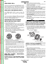
7. Disconnect the shielding gas hose from the gun
bushing, if required.
8. Connect the shielding gas hose to the new gun
bushing, if required.
9. Rotate the gun bushing until the thumb screw hole
aligns with the thumb screw hole in the feed plate.
Slide the gun receiver bushing into the wire drive
and verify the thumb screw holes are aligned.
10. Tighten the socket head cap screw.
11. Insert the welding gun into the gun bushing and
tighten the thumb screw.
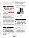
MAKING A WELD
1. Check that the electrode polarity is correct for the
process being used, then turn the power switch
ON.
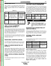
2. Set desired arc voltage tap and wire speed for the
particular electrode wire, material type and thick-
ness, and gas (for MIG and Outershield
®
) being
used. Use the Application Chart on the door inside
the wire compartment as a quick reference for
some common welding procedures.
Figure B.2b
WARNING
Return to Section TOC Return to Section TOC Return to Section TOC Return to Section TOC
Return to Master TOC Return to Master TOC Return to Master TOC Return to Master TOC