


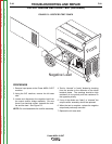
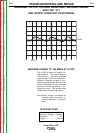
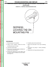
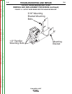
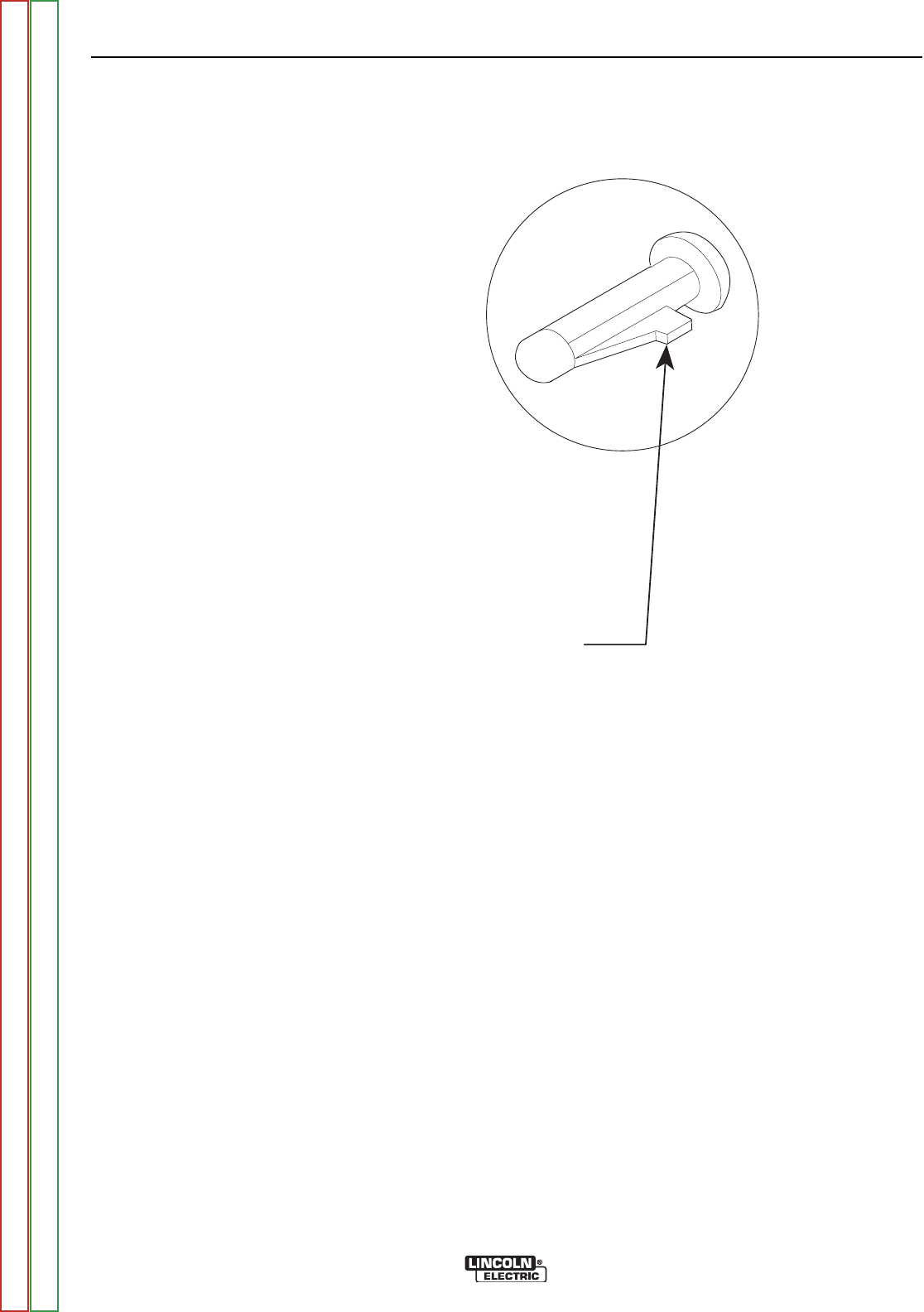
DEPRESS
LOCKING TAB ON
MOUNTING PIN
FIGURE F.8 – CONTROL BOARD MOUNTING PINS
CONTROL BOARD REMOVAL AND REPLACEMENT PROCEDURE
(continued)
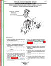
PROCEDURE
1. Remove power to the machine.
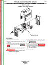
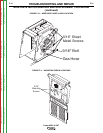
2. Using a 5/16” nutdriver, remove the three
screws securing the tool tray.
3. Locate the control board.
4. Disconnect all associated plugs and leads con-
nected to the control board.
5. Depress the retaining pins on the sides of the
four nylon mounts to release the control board.
See Figure F.8.
6. Carefully remove the control board.
7. Mount the new board to the nylon mounting
pins.
8. Reconnect any plugs or leads previously
removed.
9. Replace the tool tray previously removed.
TROUBLESHOOTING AND REPAIR
F-28 F-28
Power MIG® 215XT
Return to Section TOC Return to Section TOC Return to Section TOC Return to Section TOC
Return to Master TOC Return to Master TOC Return to Master TOC Return to Master TOC