


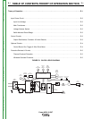
MAINTENANCE
D-2 D-2
Power MIG® 215XT
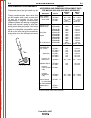
• Be sure the nozzle insulator is fully screwed
onto the gun tube and does not block the gas
holes in the diffuser.
• Slip the appropriate gas nozzle onto the nozzle
insulator. Either a standard .50" (12.7 mm) or
optional .62" (15.9 mm) I.D. slip-on gas nozzle
may be used and should be selected based on
the welding application.
• Adjust the gas nozzle as appropriate for the
GMAW process to be used. Typically, the con-
tact tip end should be flush to .12" (3.2 mm)
extended for the short-circuiting transfer
process and .12" (3.2 mm) recessed for spray
transfer.
GUN TUBES AND NOZZLES
1. Replace worn contact tips as required.
2. Remove spatter from inside of gas nozzle and from
tip after each 10 minutes of arc time or as required.
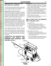
GUN CABLE CLEANING
To help prevent feeding problems, clean cable liner
after using approximately 300 pounds (136 kg) of elec-
trode. Remove the cable from the wire feeder and lay
it out straight on the floor. Remove the contact tip from
the gun. Using an air hose and only partial pressure,
gently blow out the cable liner from the gas diffuser
end.
Excessive pressure at the beginning of the clean-
ing procedure may cause the dirt to form a plug.
-----------------------------------------------------------------------
Flex the cable over its entire length and again blow out
the cable. Repeat this procedure until no further dirt
comes out. If this has been done and feed problems
are experienced, try liner replacement, and refer to
trouble shooting section on rough wire feeding.
SAFETY PRECAUTIONS
ELECTRIC SHOCK can kill.
• Have an electrician install and
service this equipment.
• Turn the input power off at the
fuse box before working on
equipment
• Do not touch electrically hot
parts.
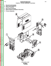
GENERAL MAINTENANCE
In extremely dusty locations, dirt may clog the air pas-
sages causing the welder to run hot. Blow dirt out of
the welder with low-pressure air at regular intervals to
eliminate excessive dirt and dust build-up on internal
parts.
The fan motors have sealed ball bearings which
require no service.
DRIVE ROLLS AND GUIDE PLATES
After every coil of wire, inspect the wire drive mecha-
nism. Clean it as necessary by blowing with low pres-
sure compressed air. Do not use solvents for cleaning
the idle roll because it may wash the lubricant out of
the bearing. All drive rolls are stamped with the wire
sizes they will feed. If a wire size other than that
stamped on the roll is used, the drive roll must be
changed.
For instructions on replacing or changing drive roll,
see Wire Drive Rolls in Operation section.
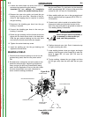
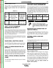
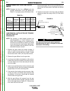
CONTACT TIP AND GAS NOZZLE
INSTALLATION
1. Choose the correct size contact tip for the electrode
being used (wire size is stenciled on the side of the
contact tip) and screw it snugly into the gas diffuser.
2. Screw the appropriate fixed gas nozzle fully onto
the diffuser. Either the standard .50" (12.7 mm)
flush nozzle or other optional flush or recessed
(spray arc) nozzle sizes may be used. (See Table
D.2 in this section.)
3. If using optional adjustable slip-on nozzles, See
Table D.2 in this section.
WARNING
WARNING
Return to Section TOC Return to Section TOC Return to Section TOC Return to Section TOC
Return to Master TOC Return to Master TOC Return to Master TOC Return to Master TOC