


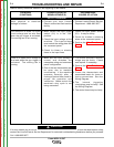
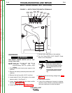
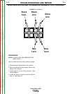
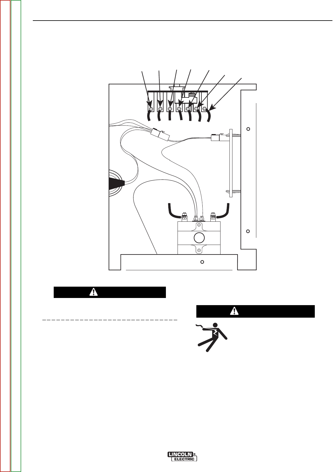
X8
X7
X6
X5X4
X3
X2
FIGURE F.1 – OUTPUT SELECTOR SWITCH TERMINALS
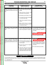
MAIN TRANSFORMER TEST (continued)
TROUBLESHOOTING AND REPAIR
F-12 F-12
Power MIG® 215XT
WARNING
PROCEDURE
THE ON/OFF POWER SWITCH will be “hot”
during these tests.
NOTE: Secondary voltages will vary
proportionately with the primary input
voltage.
1. Disconnect the main input power supply to the
machine.
2. Remove the case top and side panels with a 3/8”
nutdriver.
3. Remove the tool tray with a 5/16” nut driver.
4. Locate leads X2 thru X8 located on the output
selector switch. See Figure F.1.
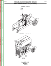
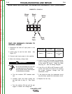
5. Locate lead X1 located on the output rectifier
assembly. See Figure F.2.
6. Locate leads X9 and X10. See Figure F.3.
7. Connect main input power to the machine.
8. Turn the Power MIG® 215XT ON/OFF Power
Switch to the ON position.
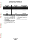
9. Carefully make the following voltage tests. See
Table F.1.
10. Turn Off the machine.
11. If any of the voltages are incorrect or missing,
check for loose or broken connections between
the main transformer and the test points.
ELECTRIC SHOCK can kill.
• Do not touch electrically live parts
such as output terminals or inter-
nal wiring.
• All input power must be electrical-
ly disconnected before proceed-
ing.
WARNING
Return to Section TOC Return to Section TOC Return to Section TOC Return to Section TOC
Return to Master TOC Return to Master TOC Return to Master TOC Return to Master TOC