


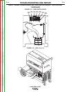

LOWER RIGHT
CASE WRAPAROUND
COVER
CAPACITOR BANK
ASSEMBLY
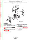
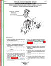
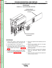
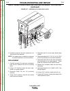
FIGURE F.14 – CAPACITOR BANK LOCATION
OUTPUT CAPACITORS REMOVAL AND REPLACEMENT PROCEDURE
(continued)
PROCEDURE
1. Using a 3/8” nutdriver, remove the lower right
side case wraparound cover. See Figure F.14.
2. Locate capacitor bank. See Figure F.14.
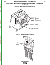
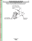
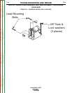
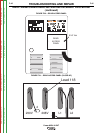
3. Label and remove the five leads connected to
the capacitor bank using a 1/2” wrench. Note
washer position upon removal. See Figure
F.15.
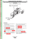
4. Using a 3/8” nutdriver, remove the three capac-
itor bank nuts and lock washers from the three
mounting bolts. See Figure F.15.
5. Remove the capacitor bank assembly from the
machine.
6. Place the new capacitor bank into its proper
location inside the machine.
7. Replace the three 3/8” nuts and lock washers
previously removed.
8. Using a 1/2” wrench, reconnect the five labeled
leads and associated washers previously
removed.
9. Replace the lower right side case wraparound
cover previously removed.
TROUBLESHOOTING AND REPAIR
F-38 F-38
Power MIG® 215XT
Return to Section TOC Return to Section TOC Return to Section TOC Return to Section TOC
Return to Master TOC Return to Master TOC Return to Master TOC Return to Master TOC