


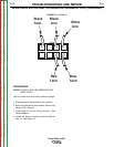
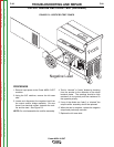
Front
-
+
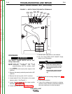
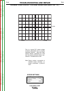
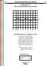
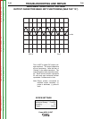
Negative Lead
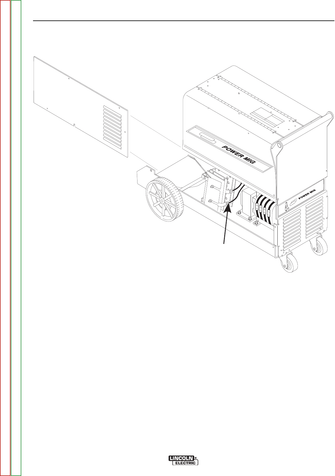
FIGURE F.6 – RECTIFIER TEST POINTS
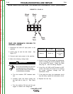
OUTPUT BRIDGE RECTIFIER TEST (continued)
PROCEDURE
1. Remove input power to the Power MIG® 215XT
machine.
2. Using the 3/8” nutdriver, remove the left case
side.
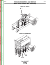
3. Locate and disconnect the negative lead from
the output rectifier bridge assembly. Be sure
there is no electrical contact between the recti-
fier and the lead. See Figure F.6.
NOTE: Do not disassemble the rectifier assembly.
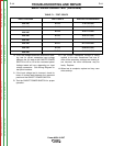
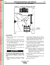
4. Test for “shorted” or “leaky” diodes by checking
from the anodes to the cathodes of the diode
heatsink plates. The readings should be high
resistance in one polarity and low resistance in
the opposite polarity.
5. If any of the diodes are “leaky” or “shorted” the
output rectifier assembly should be replaced.
6. When the test is complete, replace the negative
output lead previously removed.
7. Replace the left case side.
TROUBLESHOOTING AND REPAIR
F-20 F-20
Power MIG® 215XT
Return to Section TOC Return to Section TOC Return to Section TOC Return to Section TOC
Return to Master TOC Return to Master TOC Return to Master TOC Return to Master TOC