


TABLE OF CONTENTS - DIAGRAM SECTION
G-1 G-1
Power MIG® 215XT
Electrical Diagrams . . . . . . . . . . . . . . . . . . . . . . . . . . . . . . . . . . . . . . . . . . . . . . . . . . . . . . . . . . . . . . . . . . . . .G-1
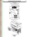
Wiring Diagram (L12184-1) . . . . . . . . . . . . . . . . . . . . . . . . . . . . . . . . . . . . . . . . . . . . . . . . . . . . . . . . . . . . .G-2
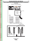
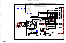
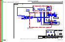
Schematic – Complete Machine (L12308-1 PG1) . . . . . . . . . . . . . . . . . . . . . . . . . . . . . . . . . . . . . . . . . . . .G-3
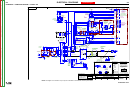
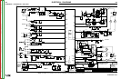
Schematic - Complete Machine with Spool Gun (L12308-1 PG2) . . . . . . . . . . . . . . . . . . . . . . . . . . . . . . .G-4
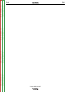
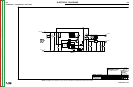
Schematic – Control PC Board * – (G4414-2 PG1) . . . . . . . . . . . . . . . . . . . . . . . . . . . . . . . . . . . . . . . . . .G-5
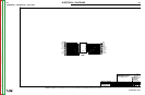
Schematic – Control PC Board – (G4414-2 PG2) . . . . . . . . . . . . . . . . . . . . . . . . . . . . . . . . . . . . . . . . . . . .G-6
Schematic – Control PC Board – (G4414-2 PG3) . . . . . . . . . . . . . . . . . . . . . . . . . . . . . . . . . . . . . . . . . . . .G-7
* NOTE: Many PC Board Assemblies are now totally encapsulated, surface mounted and or multi-lay-
ered and are therefore considered to be unserviceable. Assembly drawings of these boards are
no longer provided.
Return to Master TOC Return to Master TOC Return to Master TOC Return to Master TOC