


INSTALLATION
A-5 A-5
Power MIG® 215XT
GUN AND CABLE INSTALLATION
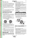
The Magnum 250L gun and cable provided with the
POWER MIG® 215XT is factory installed with a liner
for .035-.045" (0.9-1.2 mm) electrode and an .035" (0.9
mm) contact tip. Be sure that the contact tip, liner, and
drive rolls all match the size of the wire being used.
Turn the welder power switch off before installing
gun and cable.
1. Lay the cable out straight.
2. Unscrew knurled screw on the drive unit front end
(inside wire feed compartment) until tip of screw no
longer protrudes into gun opening as seen from
front of machine.
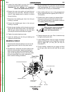
3. Insert the male end of gun cable into the Gun
Adapter casting through opening in front panel.
Make sure connector is fully inserted and tighten
knurled screw.
4. Connect the gun trigger connector from the gun and
cable to the mating receptacle inside the compart-
ment located above the gun connection made in
item 3 above. Make sure that the keyways are
aligned, insert and tighten retaining ring.
SHIELDING GAS
(For Gas Metal Arc Welding Processes)
Customer must provide cylinder of appropriate type
shielding gas for the process being used.
A gas flow regulator, for Argon blend gas, and an inlet
gas hose are factory provided with the POWER MIG®
215XT. When using 100% CO
2
an additional adapter
will be required to connect the regulator to the gas bot-
tle.
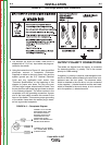
Install shielding gas supply as follows:
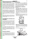
1. Set gas cylinder on rear platform of POWER MIG®
215XT. Hook chain in place to secure cylinder to
rear of welder.
WARNING
2. Remove the cylinder cap. Inspect the cylinder
valves and regulator for damaged threads, dirt,
dust, oil or grease. Remove dust and dirt with a
clean cloth.
DO NOT ATTACH THE REGULATOR IF OIL,
GREASE OR DAMAGE IS PRESENT! Inform your
gas supplier of this condition. Oil or grease in the
presence of high pressure oxygen is explosive.
3. Stand to one side away from the outlet and open the
cylinder valve for an instant. This blows away any
dust or dirt which may have accumulated in the
valve outlet.
Be sure to keep your face away from the valve out-
let when “cracking” the valve.
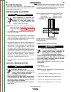
4. Attach the flow regulator to the cylinder valve and
tighten the union nut(s) securely with a wrench.
NOTE: If connecting to 100% CO
2
cylinder, an
additional regulator adapter must be
installed between the regulator and cylinder
valve. If adapter is equipped with a plastic
washer, be sure it is seated for connection
to the CO
2
cylinder.
5. Attach one end of the inlet gas hose to the outlet fit-
ting of the flow regulator, the other end to the
POWER MIG® 215XT rear fitting, and tighten the
union nuts securely with a wrench.
6. Before opening the cylinder valve, turn the regulator
adjusting knob counterclockwise until the adjusting
spring pressure is released.
7. Standing to one side, open the cylinder valve slow-
ly a fraction of a turn. When the cylinder pressure
gauge pointer stops moving, open the valve fully.
Never stand directly in front of or behind the flow
regulator when opening the cylinder valve. Always
stand to one side.
------------------------------------------------------------------------
8. The flow regulator is adjustable. Adjust it to the flow
rate recommended for the procedure and process
being used before making the weld.
AUXILIARY POWER RECEPTACLES
(15 Amp 120 Volt Receptacle) The receptacles are UL
and CSA approved.
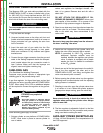
CYLINDER may explode if
damaged.
• Gas under pressure is explosive. Always
keep gas cylinders in an upright position
and always keep chained to undercarriage
or stationary support. See American
National Standard Z-49.1, “Safety in
Welding and Cutting” published by the
American Welding Society.
WARNING
WARNING
WARNING
Return to Section TOC Return to Section TOC Return to Section TOC Return to Section TOC
Return to Master TOC Return to Master TOC Return to Master TOC Return to Master TOC