


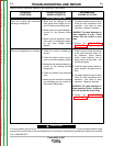
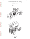
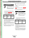
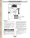
5. Make the following voltage tests:
a. Turn the machine OFF between each test.
b. Carefully insert the meter probes into the lead
side of plug J4. See Figure F.4.
c. Turn the machine ON and pull the gun trigger
to conduct the voltage test.
6. If the voltage to the wire drive motor armature is
zero, check the wires between plug J4 and the
wire drive motor. Also check the electrical con-
nector J5 for proper connections and jumper
plug. See the Wiring Diagram.
7. If all wires and connectors are good and the volt-
age to the drive motor armature is zero, the con-
trol PC board may be faulty. Replace the control
PC board.
8. If the motor is running at high speed and the
armature voltage is high and uncontrollable,
Proceed with the tachometer test.
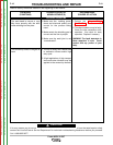
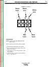
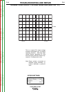
TEST FOR SUPPLY VOLTAGE TO TACHOME-
TER
1. Disconnect the main AC input power to the
machine.
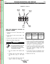
2. Locate plug J4.
3. Locate the tach leads on plug J4. See Figure
F.5.
4. Connect the main input power to the machine.
5. Make the following voltage tests:
a. Turn the machine OFF between each test.
b. Carefully insert the meter probes into the
lead side of plug J4.
6. If the 5-6 VDC is present, check the leads to the
tachometer circuit.
7. If the leads are okay and 5-6 VDC is present, the
correct voltage is being received from the con-
trol PC board. Continue with the supply voltage
to tachometer test.
8. If the 5-6 VDC is not present and the leads are
okay, the control PC board may be faulty,
replace the control PC board. Also check plug
J5 and the jumper plug. See Wiring Diagram.
WIRE DRIVE MOTOR AND TACHOMETER FEEDBACK TEST (continued)
TROUBLESHOOTING AND REPAIR
F-17 F-17
Power MIG® 215XT
ELECTRIC SHOCK can kill.
• Do not touch electrically live parts
such as output terminals or internal
wiring.
• All input power must be electrically
disconnected before proceeding.
WARNING
FROM LEAD
FROM LEAD
FROM LEAD
Black
Armature
Lead
White
Armature
Lead
2-29 VDC
(varies depending
on wire feed
speed)
ELECTRIC SHOCK can kill.
• Do not touch electrically live parts
such as output terminals or internal
wiring.
• All input power must be electrically
disconnected before proceeding.
WARNING
FROM LEAD
FROM LEAD
FROM LEAD
Black (-)
Red (+) 5-6 VDC
Return to Section TOC Return to Section TOC Return to Section TOC Return to Section TOC
Return to Master TOC Return to Master TOC Return to Master TOC Return to Master TOC