


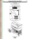
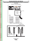
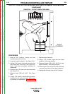
REAR
5/16" Bolts
}
}
Fan
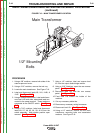
Mounting
Band
11/32"
Mounting
Nuts
Fan
Blade
Fan
Motor
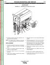
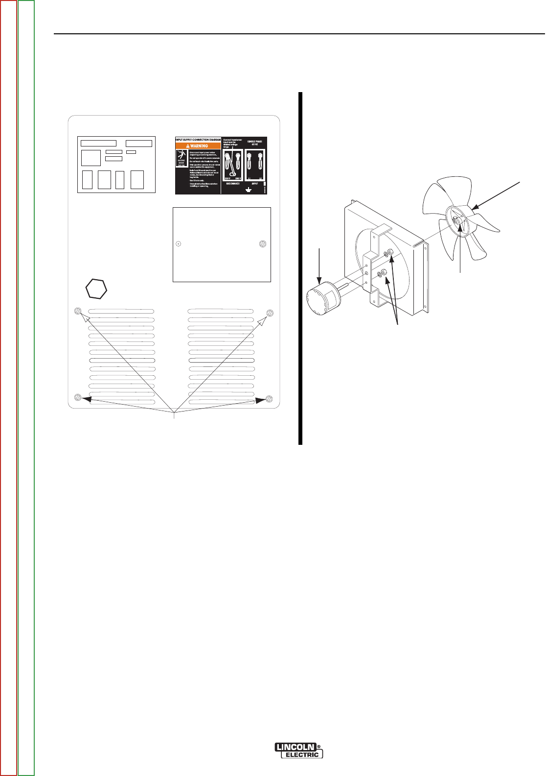
FIGURE F.22 – FAN MOUNTING BOLTS
FAN BLADE / MOTOR REMOVAL AND REPLACEMENT PROCEDURE
(continued)
PROCEDURE
1. Using a 3/8” nutdriver, remove the lower right
side of the case wraparound cover.
2. Perform the Output Capacitors Removal and
Replacement Procedure.
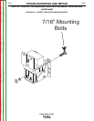
3. Using a 5/16” nutdriver, remove the four fan
mounting screws from the rear of the machine.
See Figure F.22.
4. Using an open end 11/32” wrench, remove the
two fan motor mounting nuts and lockwashers.
See Figure F.22.
5. Using a flathead screwdriver, loosen the fan
blade mounting band. See Figure F.22.
6. Pry the fan blade off of the mounting shaft.
NOTE: If fan blade cracks or breaks upon
removal, replace it.
7. Carefully maneuver the fan motor and fan blade
out of the right side of the machine.
8. Replace the fan motor and fan blade if neces-
sary.
9. Tighten the fan blade mounting band.
10. Carefully maneuver the fan assembly into its
original position.
11. Replace the two 11/32” fan motor mounting
nuts and lockwashers.
12. Replace the four 5/16” fan assembly mounting
screws in the rear of the machine.
NOTE: Make sure the fan blade is free to rotate
when all of the mounting bolts are
replaced.
13. Perform the Output Capacitors Removal and
Replacement Procedure.
14. Replace the lower right case cover.
TROUBLESHOOTING AND REPAIR
F-48 F-48
Power MIG® 215XT
Return to Section TOC Return to Section TOC Return to Section TOC Return to Section TOC
Return to Master TOC Return to Master TOC Return to Master TOC Return to Master TOC