


OPERATION
B-4 B-4
Power MIG® 215XT
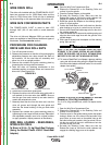
WIRE DRIVE ROLL
The drive rolls installed with the POWER MIG® 215XT
have two grooves one for .035(0.9mm) wire and the
other for .045(1.2mm) wire. Drive roll size is indicated
by the stenciling on the exposed side of the drive roll.
WIRE SIZE CONVERSION PARTS
The POWER MIG® 215XT is rated to feed .025
through .045" (0.6-1.2 mm) solid or cored electrode
sizes.
The drive roll kits and Magnum 250L gun and cable
parts are available to feed different sizes and types of
electrodes. See Accessories section.
PROCEDURE FOR CHANGING
DRIVE AND IDLE ROLL SETS
1. Turn off the power source.
2. Release the pressure on the idle roll by swinging the
adjustable pressure arm down toward the back of
the machine. Lift the cast idle roll assembly and
allow it to sit in an upright position..
3. Remove the outside wire guide retaining plate by
loosening the two large knurled screws.
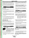
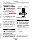
4. Twist the drive roll retaining mechanism to the
unlocked position as shown below and remove the
drive rolls. (See Figure B.2)
5. Remove the inside wire guide plate.
6. Replace the drive rolls and inside wire guide with a
set marked for the new wire size. NOTE: Be sure
that the gun liner and contact tip are also sized to
match the selected wire size.
7. Manually feed the wire from the wire reel, over the
drive roll groove and through the wire guide and
then into the brass bushing of the gun and cable
assembly.
8. Replace the outside wire guide retaining plate by
tightening the two large knurled screws. Reposition
the adjustable pressure arm to its original position
to apply pressure. Adjust pressure as necessary.
WIRE REEL LOADING - READI-REELS,
SPOOLS OR COILS
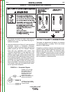
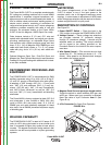
To Mount a 30 Lb. (14 kg) Readi-Reel Package
(Using the Molded Plastic K363-P Readi-Reel
Adapter:)
1. Open the Wire Drive Compartment Door
2. Depress the Release Bar on the Retaining Collar and
remove it from the spindle.
3. Place the Optional Adapter on the spindle
4. Re-install the Retaining Collar. Make sure that the
Release Bar “pops up” and that the collar retainers fully
engage the retaining ring groove on the spindle.
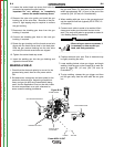
5. Rotate the spindle and adapter so the retaining spring is
at the 12 o'clock position.
6. Position the Readi-Reel so that it will rotate in a direction
when feeding so as to be de- reeled from top of the coil.
7. Set one of the Readi-Reel inside cage wires on the slot in
the retaining spring tab.
8. Lower the Readi-Reel to depress the retaining spring and
align the other inside cage wires with the grooves in the
molded adapter.
9. Slide cage all the way onto the adapter until the retaining
spring "pops up" fully.
CHECK TO BE SURE THE RETAINING SPRING HAS FULLY
RETURNED TO THE LOCKING POSITION AND HAS SECURELY
LOCKED THE READI-REEL CAGE IN PLACE. RETAINING SPRING
MUST REST ON THE CAGE, NOT THE WELDING ELECTRODE.
-----------------------------------------------------------------------------------------------
10. To remove Readi-Reel from Adapter, depress retaining
spring tab with thumb while pulling the Readi-Reel cage
from the molded adapter with both hands. Do not remove
adapter from spindle.
FIGURE B.1
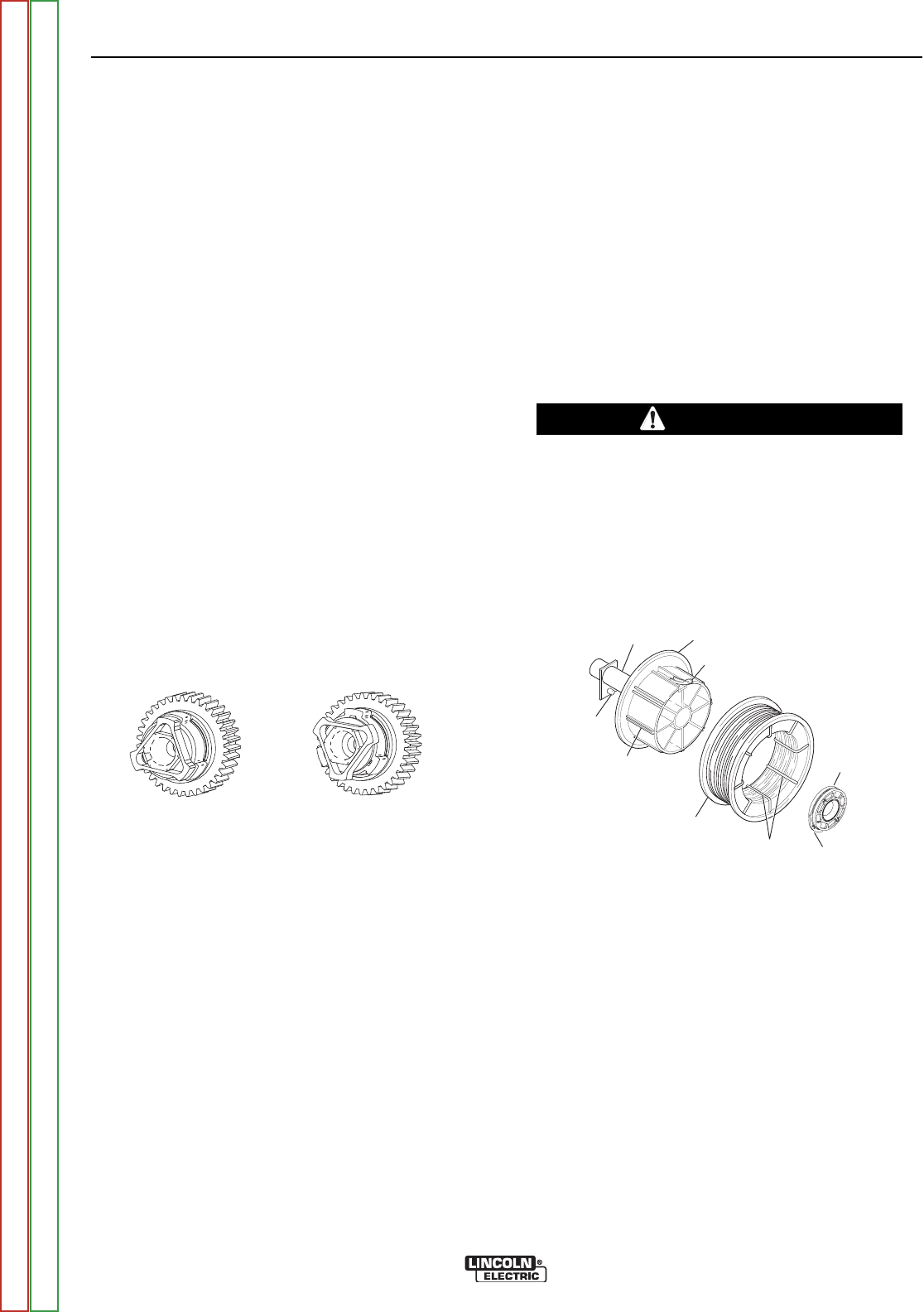
To Mount 10 to 44 Lb. (4.5-20 kg) Spools (12"/300 mm
Diameter) or 14Lb.(6 Kg) Innershield Coils:
(For 13-14 lb. (6 Kg) Innershield coils, a K435 Coil Adapter must be
used).
1
. Open the Wire Drive Compartment Door
2. Depress the Release Bar on the Retaining Collar and
remove it from the spindle.
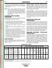
3. Place the spool on the spindle making certain the spindle
brake pin enters one of the holes in the back side of the
spool (Note: an arrow mark on the spindle lines up with
the brake holding pin to assist in lining up a hole). Be cer-
tain the wire comes off the reel in a direction so as to de-
reel from the top of the coil.
4. Re-install the Retaining Collar. Make sure that the
Release Bar “pops up” and that the collar retainers fully
engage the retaining ring groove on the spindle.
2 IN, O.D. SPINDLE
ADAPTER
RELEASE
BAR
INSIDE CAGE WIRES
READI-REEL
GROOVES
BRAKE
HOLDING
PIN
RETAINING
COLLAR
RETAINING SPRING
CAUTION
LOCKED POSITION
UNLOCKED POSITION
FIGURE B.2
Return to Section TOC Return to Section TOC Return to Section TOC Return to Section TOC
Return to Master TOC Return to Master TOC Return to Master TOC Return to Master TOC