


INSTALLATION
POWER FEED 10M SINGLE/DUAL
A-4 A-4
Return to Section TOC Return to Section TOC Return to Section TOC Return to Section TOC
Return to Master TOC Return to Master TOC Return to Master TOC Return to Master TOC
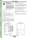
SAFETY PRECAUTION
ELECTRIC SHOCK can kill.
• Only qualified personnel should
perform this installation.
• Turn off the input power to the
power source at the disconnect
switch or fuse box before working
on this equipment. Turn off the
input power to any other equipment
connected to the welding system at
the disconnect switch or fuse box
before working on this equipment.
• Do not touch electrically hot parts.
----------------------------------------------------------------------
When using an inverter type power source like the
Power Waves, use the largest welding (electrode
and work) cables that are practical. At least 2/0
copper wire - even if the average output current
would not normally require it. When pulsing, the
pulse current can reach very high levels. Voltage
drops can become excessive, leading to poor
welding characteristics, if undersized welding
cables are used.
------------------------------------------------------------------------
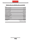
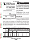
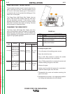
WELD CABLE SIZES
Table A.2 has the copper cable sizes recommended
for different currents and duty cycles. Lengths stipu-
lated are the distance from the welder to work and
back to the welder again. Cable sizes are increased
for greater lengths primarily for the purpose of mini-
mizing voltage in the welding circuit.
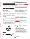
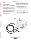
ELECTRODE LEAD
Most welding applications run with the electrode being
positive (+). For those applications, connect the elec-
trode cable between the wire feeder and the positive
(+) output stud on the power source. Connect the lug
at the other end of the electrode cable to the wire drive
feed plate. Be sure the connection to the feed plate
makes tight metal-to-metal electrical contact. The elec-
trode cable should be sized according to the specifica-
tions given in the work cable connections Table A.1.
Connect a work lead from the negative (-) power
source output stud to the work piece. The work piece
connection must be firm and secure, especially if pulse
welding is planned.
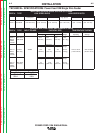
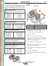
WELD CABLE SIZING
Minimum work and electrode cables sizes are as follows:
TABLE A.1
(Current (60% Duty Cycle)
MINIMUM COPPER
WORK CABLE SIZE AWG
Up To-100 Ft. Length (30 m)
400 Amps 2/0 (67 mm2)
500 Amps 3/0 (85 mm2)
600 Amps 3/0 (85 mm2)
NOTE: K1796 coaxial welding cable is recommended
to reduce the cable inductance in long distance Pulse
or STT applications up to 300 amps.
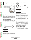
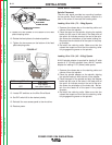
WELD CABLE CONNECTION
Connect a work lead of sufficient size and length (Per
Table A.1) between the proper output terminal on the
power source and the work. Be sure the connection to
the work makes tight metal-to-metal electrical contact.
To avoid interference problems with other equipment
and to achieve the best possible operation, route all
cables directly to the work or wire feeder. Avoid exces-
sive lengths and do not coil excess cable.
CAUTION
Amperes
325
350
400
400
500
Percent
Duty
Cycle
100
60
60
100
60
200 to 250 Ft.
61 to 76 m
3/0
3/0
4/0
4/0
4/0
150 to 200 Ft.
48 to 61 m
2/0
2/0
3/0
3/0
3/0
100 to 150 Ft.
31 to 48 m
2/0
2/0
2/0
3/0
3/0
50 to 100Ft.
15 to 31 m
2/0
1/0
2/0
3/0
2/0
0 to 50 Ft.
0 to 15 m
2/0
1/0
2/0
3/0
2/0
RECOMMENDED CABLE SIZES (RUBBER COVERED COPPER - RATED 75°C)**
CABLE SIZES FOR COMBINED LENGTHS OF ELECTRODE AND WORK CABLES
TABLE A.2
** Tabled values are for operation at ambient temperatures of 40°C and below. Applications above 40°C may require cables larger than
recommended, or cables rated higher than 75°C.