


POWER FEED 10M SINGLE/DUAL
INSTALLATION
AA-6 AA-6
Return to Section TOC Return to Section TOC Return to Section TOC Return to Section TOC
Return to Master TOC Return to Master TOC Return to Master TOC Return to Master TOC
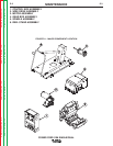
WIRE DRIVE GEAR RATIO (HIGH OR
LOW SPEED)
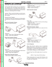
The speed range capability and drive torque of the
Power Feed wire drives can be easily and quickly
changed by changing the external drive gear. The
Power Feed Wire Feeders are shipped with both high
speed and a low speed gears. As shipped from the fac-
tory, the low speed (high torque) gear is installed on
the feeder. If this is the desired gear ratio, no changes
need be made.
If a change in gear ratio is desired, the systems needs
to be made aware of which gear has been installed on
the Wire Drive, low or high speed. This is accom-
plished through the selection of a dip switch on the wire
drive PCB.
SELECTING THE PROPER GEAR RATIO
See Technical Specifications at the front of the
Installation Section for feed speed and wire size capa-
bilities with high and low speed gear ratios. To deter-
mine whether you should be using the high or low
speed ratio use the following guidelines:
• If you need to operate at wire feed speeds above
800 IPM (20 m/m), you will need to install the high
speed gear (large 30 tooth, 1.6 inch diameter gear).
• If you do not need to run at wire feed speeds in
excess of 800 IPM (20 m/m), you should use the low
speed gear (small, 20 tooth, 1.1 inch diameter gear).
Using the low speed ratio will provide the maximum
available wire driving force.
Note: If you are feeding only small diameter wires you
may, at your option, install the high speed ratio.
Work Voltage Sensing
The standard Power Wave 455’s default to the work
stud (work sense lead disabled)
For processes requiring work voltage sensing, connect
the (21) work voltage sense lead (K940) from the
Power Wave work sense lead receptacle to the work
piece. Attach the sense lead to the work piece as close
to the weld as practical, but not in the return current
path. Enable the work voltage sensing in the Power
Wave as follows:
• Do not touch electrically live parts or
electrodes with your skin or wet
clothing.
• Insulate yourself fr
om the work and
ground.
• Always wear dry insulating gloves.
-----------------------------------------------------------
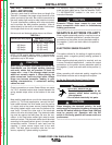
1. Turn off power to the power source at the disconnect
switch.
2. Remove the front cover from the power source.
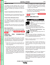
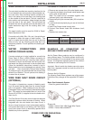
3. The control board is on the left side of
the power source. Locate the 8-position
DIP switch and look for switch 8 of the
DIP
switch.
4. Using a pencil or other small object,
slide the switch right to the OFF position
if the work sense lead is NOT connect-
ed. Conversely, slide the switch left to
the ON position if the work sense lead is
present.
5. Replace the cover and screws. The PC board will
“read” the switch at power up, and configure the
work voltage sense lead appropriately.
Electrode Voltage Sensing
Enabling or disabling electrode voltage sensing is
automatically configured through software. The 67
electrode sense lead is internal to the cable to the wire
feeder and always connected when a wire feeder is
present.
I
mportant: The electrode polarity must be config-
ured at the feed head for all semi-automatic
processes. Failure to do so may result in extreme-
ly high welding outputs.
------------------------------------------------------------------------
WARNING
O
N
1 2 3 4 5 6 7 8
CAUTION