


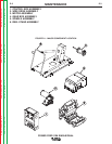


POWER FEED 10M SINGLE/DUAL
INSTALLATION
AA-3 AA-3
Return to Section TOC Return to Section TOC Return to Section TOC Return to Section TOC
Return to Master TOC Return to Master TOC Return to Master TOC Return to Master TOC
SAFETY PRECAUTION
ELECTRODE ROUTING
The electrode supply may be either from reels, Readi-
Reels, spools, or bulk packaged drums or reels.
Observe the following precautions:
a) The electrode must be routed to the wire drive unit
so that the bends in the wire are at a minimum,
and also that the force required to pull the wire
from the reel into the wire drive unit is kept at a
minimum.
b) The electrode is “hot” when the gun trigger is
pressed and must be insulated from the boom and
structure.
c) If more than one wire feed unit shares the same
boom and are not sharing the some power source
output stud, their wire and reels must be insulated
from each other as well as insulated from their
mounting structure.
CONTROL CABLE
CONTROL CABLE CONNECTIONS
• All system control cables are the same.
• All control cables can be connected end to end to
extend their length.
• All system equipment must be connected to a control
cable.
NOTE: The maximum cable length between Power
Source and Wire Feeder is 100'(30.5m).
ELECTRIC SHOCK can kill.
• Only qualified personnel should per-
form this installation.
• Turn off the input power to the power
source at the disconnect switch or
fuse box before working on this equip-
ment. Turn off the input power to any
other equipment connected to the
welding system at the disconnect
switch or fuse box before working on
this equipment.
• Do not touch electrically hot parts.
• Always connect the Power Wave grounding lug
(located inside the reconnect input access door) to
a proper safety (Earth) ground.
----------------------------------------------------------------------------------------
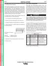
Typical Bench Feeder Connection:
Control cable is connected from the Power Wave 455
output receptacle to the input receptacle on the back of
the Wire Drive.
CONTROL CABLE SPECIFICATIONS
It is recommended that only genuine Lincoln control
cables be used at all times. Lincoln cables are specifi-
cally designed for the communication and power
needs of the Power Wave 455 / Power Feed system.
The use of non-standard cables, especially in lengths
greater than 25 feet(7.6m), can lead to communication
problems (system shutdowns), poor motor accelera-
tion (poor arc starting) and low wire driving force (wire
feeding problems).
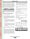
Lincoln control cables are copper 5 conductor cable in
a SO-type rubber jacket. There is one 20 gauge twist-
ed pair for network communications. This pair has an
impedance of approximately 120 ohms and a propaga-
tion delay per foot of less than 2.1 nanoseconds.
There are two 12 gauge conductors that are used to
supply the 40 VDC to the network. The fifth wire is 18
gauge and is used as an electrode sense lead.
AVAILABLE CABLE ASSEMBLIES
K1543 Control cable only. Available in lengths of
8'(2.4m), 16'(4.9m), 25'(7.6m), 50'(15.2m) and
100'(30.5m).