


Return to Section TOC Return to Section TOC Return to Section TOC Return to Section TOC
Return to Master TOC Return to Master TOC Return to Master TOC Return to Master TOC
TROUBLESHOOTING & REPAIR
F-4 F-4
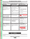
PROBLEMS
(SYMPTOMS)
POSSIBLE AREAS OF
MISADJUSTMENT(S)
RECOMMENDED
COURSE OF ACTION
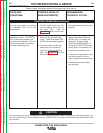
FUNCTION PROBLEMS
Major physical or electrical damage
is evident when the sheet metal
cover(s) are removed.
1. Contact your local authorized
Lincoln Electric Field Service
Facility for assistance.
1. Contact the Lincoln Electric
Service Department, 1-888-935-
3877.
No control of wire feed speed. All
STATUS LEDs are steady green.
The preset wire feed speed is
adjustable on the Control Box.
1. Check for a mechanical restric-
tion in the wire feed path.
1. Perform the Tach Feedback
Test.
2.
The wire drive feedhead board
may be faulty.
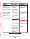
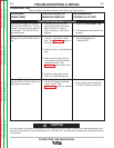
No welding arc voltage when the
gun trigger is activated. The wire
feeds normally and the gas sole
-
noid functions properly. The STA-
TUS LEDs are steady green on the
wire drive unit and the Control Box.
1. The Power source may unable
to produce welding output due to
a thermal fault or other malfunc-
tion. Check STATUS LED on
Power Wave 455 machine. See
Power Wave 455
Troubleshooting.
1. Make certain the Power W
ave
455M power source is func-
tioning correctly.
2. The wire drive feedhead board
may be faulty
.
3. The Control Box control board
may be faulty.
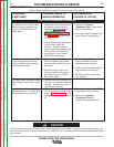
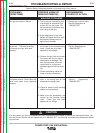
The wire feed speed does not
change when welding current is
established. The WFS stays at the
run-in speed. The STATUS LEDs
are steady green.
1. The run in and weld wire feed
speeds may be set to the same
value. Set run in speed to a
value that gives best starting
results.
1. Perform the Current
Transducer T
est. In Power
Wave 455 service manual.
2.
If the run in wire feed speed can-
not be adjusted, perform the
Tach Feedback Test and also
the Drive Motor Test.
3. The wire drive feedhead board
may be faulty
.
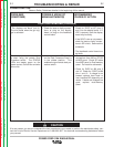
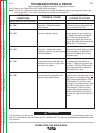
No wire feed, solenoid or arc volt-
age. The STATUS LED’s are
steady green.
1. The gun trigger may be faulty.
Check or replace.
2. Make certain the Control Box is
configured for a wire feeding
mode.
3. Check option panel connections
and switch(s) for proper opera-
tion.
1. Check the continuity of leads
from the gun trigger receptacle
to plug J85. See wire drive
wiring diagram.
2. The wire drive feedhead board
may be faulty.
3. The Control Box control board
POWER FEED 10M SINGLE/DUAL
CAUTION
If for any reason you do not understand the test procedures or are unable to perform the test/repairs safely, con-
tact the Lincoln Electric Service Department at 1-888-935-3877 for electrical troubleshooting assistance before
you proceed.
POWER FEED 10M
Observe Safety Guidelines detailed in the beginning of this manual.