


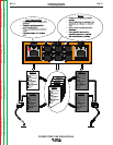

POWER FEED 10M SINGLE/DUAL
OPERATION
BB-8 BB-8
Return to Section TOC Return to Section TOC Return to Section TOC Return to Section TOC
Return to Master TOC Return to Master TOC Return to Master TOC Return to Master TOC
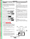
LIMIT SETTING
The MSP4 can be optionally configured to limit the
operator’
s range of control of any weld parameter
(weld WFS, arc control, etc.). Limits are only available
with the Dual Procedure/Memory Panel.
MACHINE SETUP/USER PREFERENCES
The MSP4 can be used to configure and troubleshoot
the machine.
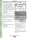
ACCESSING THE MACHINE SETUP MENU
To access the Machine Setup menu, press both MSP4
push buttons simultaneously.
The MSP4 7-segment
display will display the first user preference, "P.0", and
the SETUP LED will illuminate.
• Pressing the left MSP4 pushbutton will exit the entire
Machine Setup menu while in the P.0 user prefer-
ence.
• Turning the MSP4 encoder knob will select other
available User Preferences.
• To exit the User Preference Menu, either rotate the
MSP4 encoder until P.0 is displayed and press the
left MSP4 pushbutton or press both MSP4 push but-
tons
simultaneously at any time.
SETUP FEATURES MENU
The Setup Menu gives access to the set-up configuration.
Stored in the setup configuration are user parameters that
generally need to be set only at installation. The para-
meters are grouped as follows:
• P.1 through P.99 Unsecured Parameters (always
adjustable)
• P.101 through P.199 Diagnostic Parameters (always
read only)
• P.501 through P.599 Secured Parameters (accessi-
ble only though a p.c. or palm application.)
To access the setup menu, press the right and left buttons
of the MSP4 panel simultaneously. Note that the setup
menu cannot be accessed if the system is welding, or if
there is a fault (The status LED is not solid green).
Change the value of the blinking parameter rotating the
SET knob.
To exit the setup menu at any time, press the right and left
buttons of the MSP4 panel simultaneously. Alternately, 1
minute of inactivity will also exit the setup menu.
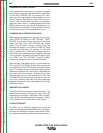
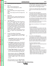
The following list includes all possible parameters in
ArcLink equipment. Not all of the parameters listed
may appear for your system. Refer to the (TABLE B.1)
for active parameters.
PARAMETER
P. 0
P. 1
P. 2
P. 3
P. 4
P. 5
P. 6
P. 7
P. 8
P.9
P. 11
P.12
P.13
P.80
P.99
DESCRIPTION
Exit set-up menu
WFS Units
Arc Display Mode
Display Power
Trigger Memory Recall
Trigger Procedure Change
Stall Factor Adjustment
Gun Offset Adjustment
TIG Gas Control
Crater Delay
Set Timers
Travel Options
Adjust Arc Force
Sense From Studs
Show Test Modes
View Diagnostics
View Event Logs
View Fatal Logs
View Software Version
View Hardware Version
View Welding Software
View Ethernet IP Address
View Power Source Type
P.100
P.101
P.102
P.103
P.104
P.105
P.106
P.107
Unsecured Parameters
Diagnostic Parameters
PF*-10M (All Models)
√
√
√
√
√
√
√
√
√
√
√
√
√
√
√
√
√
√
√
√
√
√
√
√
√
√
√
√
√
√
√
√
√
√
√
√
√
PF*-15M
√
√
√
PF*-10A
√
√
√
√
√
√
√
* PF= POWER FEED