


POWER FEED 10M SINGLE/DUAL
OPERATION
BB-14 BB-14
Return to Section TOC Return to Section TOC Return to Section TOC Return to Section TOC
Return to Master TOC Return to Master TOC Return to Master TOC Return to Master TOC
Recalling from Memory
To recall the contents of a memory into the active proce-
dure, momentarily push the desired memory button (for
less than 2 seconds). The saved parameters will be
copied into the active procedure, and the LED of the
memory button will light indicating the source of the infor-
mation. As with saving to memory, this light will remain lit
as long as the contents of the source memory remain
equal to the contents of the associated procedure.
If a constant current mode is saved to memory with the
power source in the "on" state, the "on" status will be
changed to "off" when the procedure is recalled. This pre-
vents a potential safety hazard if a memory button is
pushed and the power source unexpectedly turns on.
2 STEP / 4 STEP OPERATION
The Wire Drive has a 2 Step / 4 Step switch located
near the gun connector. 2-Step Trigger Mode operation
requires the operator hold the gun trigger closed in
order to weld. 4-Step Trigger Mode eliminates the need
to hold the gun trigger closed while welding. User-
selectable 4-step modes with or without current inter-
lock. The switch in the down position will enable 2-Step
operation and in the up position enables 4 -Step oper-
ation. This switch has no effect in CC modes of opera-
tion, such as stick welding. Both 2 and 4 -Step can be
operated in Synergic and Non-Synergic modes. In a
Synergic mode, machine output tracks Wire Feed
Speed (WFS) during welding. In Non-Synergic modes,
machine output is independent of WFS.
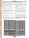
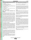
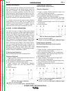
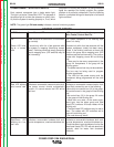
2 Step Synergic Operation:
Without Start/Crater/Burnback functions active
Waveform Sequence:
1. Trigger is pulled; Preflow sequence begins and runs
until preflow timer expires.
2. Strike sequence initiates until Arc is established.
3.
Arc established; Weld sequence begins.
4. Trigger released (Arc extinguished); Postflow
sequence begins and runs until postflow timer
expires.
5. End of sequence.
WFS vs. Work point Waveform
= solid line represents WFS
---=
dashed line represents Work point or Machine Output
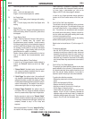
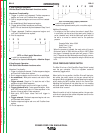
2 Step Synergic Operation:
With Burnback function active.
Waveform Sequence:
1. Trigger is pulled; Preflow sequence begins and
runs until preflow timer expires.
2. Run-In sequence initiates until Arc is established.
3. Arc established; W
eld sequence begins.
4. Trigger released (Arc extinguished); Burnback
sequence begins and runs until burnback timer
expires.
5. Postflow sequence begins and runs until postflow
timer expires.
6. End of sequence.
WFS vs. Work point (Output) Waveform
1 2 34 5
1 2 3 4 5 6
= solid line represents WFS
---=
dashed line represents Work point or Machine Output
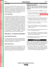
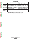
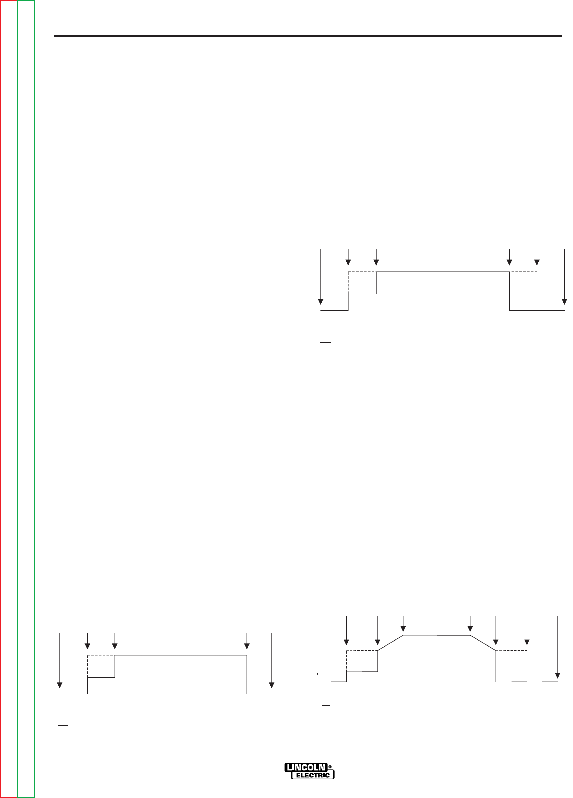
2 Step Synergic Operation:
With Start/Crater/Burnback functions active.
Waveform Sequence:
1. Trigger is pulled; Preflow sequence begins and
runs until preflow timer expires.
2. Run-In sequence initiates until Arc is established.
3. Arc established; Start sequence begins and runs
for the amount of time set.
4. Weld sequence begins.
5.
Trigger released; Crater sequence begins and
runs until crater timer expires.
6. Arc Extinguished; Burnback sequence begins and
runs until burnback timer expires.
7. Postflow sequence begins and runs until postflow
timer expires.
8. End of process.
WFS vs. Work point (Output) Waveform
= solid line represents WFS
---=
dashed line represents Work point or Machine Output
1 2 3 4 5 6 7 8