


POWER FEED 10M SINGLE/DUAL
OPERATION
B-23 B-23
Return to Section TOC Return to Section TOC Return to Section TOC Return to Section TOC
Return to Master TOC Return to Master TOC Return to Master TOC Return to Master TOC
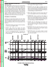
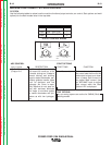
200
----
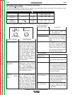
WFS AMPS
V
OLTS TRIM
LESS
D
EPOSITION
MORE
D
EPOSITION
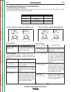
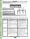
EFFECT / RANGE
PEAK CURRENT
BACKGROUND
CURRENT
TAIL OUT
(STT ll MODES
ONLY)
DESCRIPTION
Peak Current acts similar to an
arc pinch control. Peak Current
sets the arc length and pro-
motes good fusion. Higher
peak current levels will cause
the arc to broaden momentarily
while increasing arc length. If
set too high, globular transfer
may occur. Setting it too low
may cause instability and wire
stubbing. Best practice is to
adjust for minimum spatter and
puddle agitation.
Background Current controls
the overall heat input in the
weld. High background cur-
rents flatten the weld bead, and
low background currents create
a taller rounded contour.
Tail out provides additional
power without the molten
droplet becoming too large.
Increase as necessary to add
heat input without increasing
arc length. Often this results in
faster travel speeds. Note that
as tail out increases, the peak
current and/or background cur-
rent may need to be reduced.
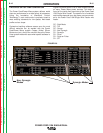
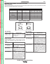
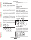
PREFLOW TIME
0 - 10 seconds
RUN-IN WFS:
Off, 50 to150 in/min.
Start Procedure
FUNCTION
Adjusts the time the gas flows
after the trigger is pulled and
prior to feeding wire.
Run-in sets the wire feed speed
from the time the trigger is
pulled until an arc is estab-
lished.
The Start Procedure controls
the WFS. Trim at a specified
time at the beginning of the
weld. During the start time, the
machine will ramp up or down
from the Start Procedure to the
preset Welding Procedure.
START OPTIONS
PARAMETER RANGE
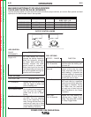
Postflow Time:
0 to 10 seconds
Crater Procedure
Burnback:
0 to .25 Seconds
Spot Timer:
0 to 10 Seconds
FUNCTION
Adjusts the time that shielding gas
flows after the welding output turns
off.
Crater Procedure controls the
WFS and volts for a specified time
at the end of the weld after the trig-
ger is released. During the Crater
time, the machine will ramp up or
down from the Weld Procedure to
the Crater Procedure.
The burnback time is the amount of
time that the weld output continues
after the wire stops feeding. It pre-
vents the wire from sticking in the
puddle and prepares the end of the
wire for the next arc start.
Adjusts the time welding will con-
tinue even if tigger is still pulled.
This option has no effect in 4-Step
Trigger Mode.
END OPTIONS
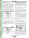
MACHINE FUNCTIONALITY BY WELD PROCESS
STT AND STT II (SYNERGIC)
Use the following tables to review how the machine functions (output controls, arc control, Start options and weld
options) for the weld modes listed in the top table.
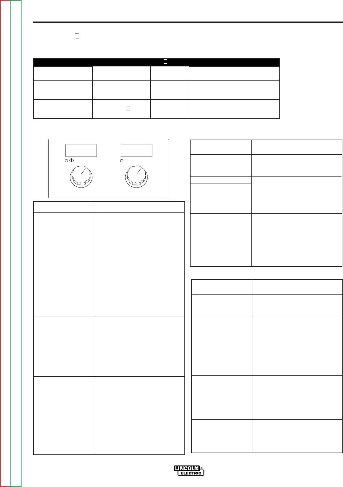
OUTPUT CONTROL KNOBS (There is no Voltage control when STT welding.)
MATERIAL
STEEL
STAINLESS
STEEL
ST
AINLESS
GAS
Ar/CO
2
CO
2
Ar/CO
2
CO
2
PROCESS
STT
STT II
WIRE SIZE
0.035 0.045 0.052
109 125 125
110 126 126
STT AND STT II MODES